TM 1-1520-240-10
3-2-13
CONTROLS/
INDICATOR
FUNCTION
POS. 1-6
In single channel mode, preset
frequencies are selected or
loaded. In FH or FM-M mode,
frequency hopping nets are se-
lected.
CUE
Used by a non-ECCM radio to
signal to CUE or ECCM radio.
IFM RF Selector
OFF
(Bypass) - 10 watts
LO
(Low Power) -2.5 watts
NORM
(Normal) -10 watts
HI
(High power) - 40 watts
Display
The display generally operates
in conjunction with the key-
board. Other displays may be
selected by the FUNCTION
and MODE selectors.
Keyboard
A 15- button array of switches
in a 4 x 4 matrix, used to insert
data or select data for display.
The keyboard is comprised of
10 numerical buttons, three
special functions, and two
command buttons.
Switches 1 - 9
Used to key in frequencies,
load time information, or off-
sets.
CLR
Used to zeroize the display or
to clear erroneous entries.
0 (H-LD)
Used to enter zeroes. Second
function (hold) initiates transfer
of ECCM parameters.
STO/ENT
Initiate entry of all data by key-
board entry. Its second func-
tion is to store a received Hop-
set or Lockout Set held in hold-
ing.
FREQ
Display the current operating
frequency during single chan-
nel (manual or preset) opera-
tion.
CONTROLS/
INDICATOR
FUNCTION
SEND/OFST
Modify a single channel oper-
ating frequency, manually se-
lect or preset, to include offsets
of + 5 or +10 kHz. It has a sec-
ond function on initiating an
ERF Transmission if a Hopset
or Lockout.
Set is in the holding memory
and the Mode Switch is in the
FH-M position.
TIME
Used to display or change the
time setting maintained within
each RT.
FILL
Used to fill ECCM parameters
from an external fill device.
Entry of ECCM parameters is
initiated by the H-LD button on
the keyboard with the FUNC-
TION switch in LD or LD-V.
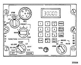
Figure 3-2-6. VHF/FM Radio Set (AN/ARC-201)
3-2-18. Voice Security Equipment TSEC/KY-58.
The voice security equipment is user with the FM band
of the No. 1 VHF AM/FM radio to provide secure two-way
communication. The equipment is controlled by the re-
mote control unit (RCU) Z-AHP mounted on the right side
of the console. The POWER switch must be at ON, re-
gardless of the mode of operation, whenever the equip-
ment is installed. Power to operate the voice security
system is supplied by the No. 2 DC bus through the
COMM KY-28 circuit breaker on the No. 2 PDP.