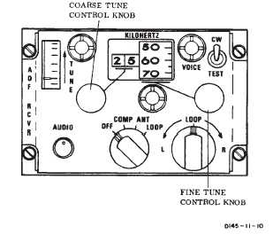
TM 1-1520-240-103-3-3CONTROLS/INDICATORFUNCTIONAUDIO ControlAdjusts audio level inCOMP position. Used asRF gain control in LOOPor ANT position.LOOP SwitchWhen function switch isset to LOOP, LOOPswitch enables manualrotation of ADF loop an-tenna and bearing indi-cator pointer left or rightfor manual directionfinding, or when homingto a radio station. Re-turning LOOP switch tocenter position stopsrotation of bearing indi-cator pointer at any de-sired position.Figure 3-3-2. Direction Finder ControlCONTROLS/INDICATORFUNCTIONCoarse Tune ControlTunes receiver in 100kHz steps as indicatedby first two digits of KI-LOHERTZ indicator.Fine Tune ControlProvides selection of 10kHz digits (continuoustuning) as indicated bylast two digits of KI-LOHERTZ indicator.CONTROLS/INDICATORFUNCTIONKILOHERTZ IndicatorDisplays operating fre-quency to which receiv-er is tuned.TUNE MeterProvides indication ofrelative signal strengthwhile tuning receiver tospecific radio signal.CW-VOICE-TEST SwitchThree position toggleswitch. Spring-loadedfrom TEST.CWEnables the beat fre-quency oscillator (BFO)to permit tuning to con-tinuous wave stations.VOICEEnables the set to oper-ate as an AM receiver.TESTRotates the bearing indi-cator approximately180_ to check operationof the set. The TESTswitch functions whenthe function switch is atCOMP only.3-3-7. Normal Operation — Direction FinderSet. The following paragraphs discuss ADF set opera-tion.a. Starting.(1)Interphone control panel - Receivers NAVswitch — ON.(2)Mode switch — ON.(3)CW-VOICE-TEST — CW or VOICE.(4)Tune controls — Set frequency. Tune formaximum signal strength on the tuning meter.(5)AUDIO control — Adjust.b. ADF Operation.(1)VOR ADF switch on HSI MODE SELECTpanel — Press, if ADF segment is not lit.(2)Check for the correct bearing indication, onHSI No. 2 bearing pointer.c. Radio Receiver Operation.(1)Function switch — ANT(2)Tune control — Set frequency; then tune formaximum signal strength on the tuning meter.d. Aural Null.(1)CW-VOICE-TEST switch — CW.(2)Function switch — LOOP.(3)Loop switch — Rotate for audio and tuneindicator null. Release switch. Observe bearing to stationon indicators. Two null positions, 180_ apart, may beobtained.
Integrated Publishing, Inc. - A (SDVOSB) Service Disabled Veteran Owned Small Business