TM 1-1520-240-10
3-4-3
3-4-3. Normal Operation — Transponder System.
The following steps provide transponder system operat-
ing procedures.
a. Starting.
(1)
Move the MASTER switch from OFF to
STBY. If the aircraft is so equipped, observe that the
STBY light on the aircraft advisory panel comes on. Also,
note that the NO GO light is on.
(2)
Allow 2 minutes for warmup.
(3)
Select the codes assigned for use in modes
1 and 3/A by depressing and releasing the pushbutton for
each switch until the desired number shows.
(4)
Operate the PRESS-TO-TEST feature of
the lamp indicators.
(5)
Place the ANT switch BOT.
(6)
Move the MASTER switch from STBY to
NORM.
(7)
Hold the M-11 switch to TEST, observe that
the TEST/GO indicator lights.
(8)
Restore the M-1 switch to ON.
(9)
Repeat (7) and (8) above for the M-2, M-3/A
and M-C mode switches.
(10) Place the ANT switch TOP.
(11) Repeat (7), (8), and (9) above.
(12) Place the ANT switch DIV.
(13) Repeat (7), (8), and (9) above.
NOTE
If KIT1C is not installed or keyed the following
steps are not required.
(14) Set the MODE 4 rotary switch to A. If the
external computer is used, set a code in it.
(15) Set the MODE 4 AUDIO/LIGHT/OUT switch
to OUT.
(16) Hold the MODE 4 TEST/ON/OUT switch to
TEST.b.
(1)
If the computer is used, observe that the
TEST GO indicator lights. If the computer is not con-
nected, observe that the TEST/MON/NO GO indicator
lights and the KIT STATUS indicator lights.
(2)
Observe that the MODE 4 REPLY light and
CAUTION light (on a separate “panel”) do not light.
(3)
Restore the MODE 4 TEST/ON/OUT switch
to ON for computer use, or to OUT if no computer is
used.
c. Stopping.
(1)
If code retention is desired:
(a)
MODE 4 CODE selector switch —
HOLD, then release.
(b)
MODE 4 CODE selector switch — A or
B, as applicable.
(c)
MASTER control switch — OFF.
(2)
If code retention is not desired:
(a)
MODE 4 CODE selector switch —
ZERO.
(b)
MODE 4 CODE selector switch — A or
B, as applicable.
(c)
MASTER control switch — OFF.
d. Turn KYK-13 Mode switch to OFF.
e. Disconnect KYK-13 from aircraft receptacle.
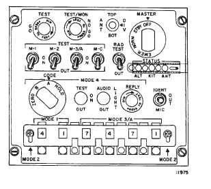
Figure 3-4-1. AN/APX-100 Control Panel
3-4-4. GPS Zeroize Switch. (fig. 2-1-8)
The GPS Zeroize switch is located on center instrument
panel, right side of AN/APR-39AV(1) Indicator, and is
used to erase any crypto data and all navigational infor-
mation stored in the GPS Receiver.
This zeroize switch consists of a guarded toggle switch.
3-4-5. Normal Operation - GPS Zeroize Switch.
NOTE
Aircraft battery must be connected, or power
applied to aircraft.
a. Lift protective guard from zeroize toggle switch
and activate switch.
b. If GPS receiver is on, turn Data Switch to Stat.
Observe message on Page 1, Line 2.