TM 1-1520-240-10
2-3-9
This provides the FADEC system with back up electrical
power in the event of a HMU integral alternator failure
thus preventing loss of the PRI mode. Placing the B/U
PWR switch to OFF will reduce operating time on the
FADEC circuitry. The B/U PWR switch should always be
ON during engine operation.
d.
OSPD 1, 2 Switch. The Over Speed test switch is
a three position switch used to test the FADEC over-
speed system. In the event of a NR overspeed of 114.8
percent, FADEC reduces fuel flow to a ground idle condi-
tion. The system remains activated until the overspeed
condition no longer exists, and will re-activate as soon as
an overspeed re-occurs. The system contains provisions
to inhibit overspeed trip command if the other engine has
experienced a overspeed trip condition. To prevent inad-
vertent operation during flight, this test is locked out if NR
is greater than 81.3 percent. When performing an over-
speed test with the engine running and the RRPM
79.0$1%, pressing the test switch to 1 or 2, lowers the
overspeed trip threshold to 79.0$1% NR. At this time the
system senses an overspeed and reduces the fuel flow.
e.
LOAD SHARE, PTIT/TRQ Switch. The primary
FADEC system provides pilot selectable engine torque
PTIT matching to govern the engines. Torque matching
is normally the preferred option. The selected parameter
is constantly compared between the two engines until the
RRPM stabilizes at datum figure. The PTIT option may
be used when one engine is running hot. N1 matching is
engaged automatically if the selected matching mode
fails.
f.
ENG START Switch. It is a three position switch,
spring loaded to the center position, labeled 1 and 2. It is
used to commence the start sequence on the respective
engine.
2-3-33. DECU Unit. 714A
The two airframe mounted DECU’s, one for each engine,
contain the primary and reversionary mode electronics.
The DECUs are located on the left (sta 390) and right (sta
410) side of the aft cabin.
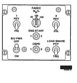
Figure 2-3-6. FADEC Panel 714A
2-3-34. BIT. 714A
The DECU contains a two-digit BIT display. When active,
the display indicates the operating status of the FADEC
system and power assurance test results. A complete list
of the FADEC BIT fault codes are located at Table 2-3-1.
The fault monitoring carried out by the DECU consists of:
a.
Power up tests.
b.
Fault tests designed to discover dormant faults.
c.
A set of repeated monitoring tests to detect faults
occurring during normal operation.
Fault information for the previous or current engine cycle
can be seen on the DECU BIT display. The last engine
cycle is reset on the first occurrence of start mode and not
on engine shutdown. During engine shutdown (when
ECL is at STOP or N1 is less than 10 percent) faults are
not stored. Fault indications are stored in the DECU and
are retained throughout the life of the control unit. How-
ever, fault information prior to the previous cycle can only
be accessed with specialized test equipment. During en-
gine start the DECU BIT displays 88 for satisfactory test
or if the test fails, a fault code. Faults are classified as
either “HARD” or “SOFT”. In primary mode a hard fault
will cause the FADEC to transfer to Reversionary , while
in Reversionary a hard fault will cause the FADEC to “fail
fixed” to a constant power condition. If a hard fault occurs
in Primary after a hard fault exists in reversionary then
the primary will fail fixed. In the event of a soft fault the
FADEC will remain in the mode it was in prior to the fault
but there may be some degradation or redundancy. All
soft faults are less severe than a hard fault since the
FADEC will not switch modes due to a soft fault.
The activation of the BIT display is dependent upon the
position of the ECL as follows:
a.
With the ECL at STOP, the fault information for
the last engine cycle and current faults are displayed.
b.
When the ECL is positioned at GROUND only
current faults are displayed.
c.
When the ECL is positioned at FLIGHT the dis-
play will be turned off except as required for Power Assur-
ance Test (PAT).
2-3-35. Starting in Primary Mode. 714A
CAUTION
The (P3) compressor pressure signal line
going to the DECU contains a manually
operated moisture drain valve. This valve
shall not be drained while the engine is
running.
NOTE
Engine may not start if REV fail caution is
illuminated.
In primary mode, engine start is initiated with the ECL in
the GND position. Select and hold the respective ENG
START switch and allow the engine to accelerate to 10