TM 1-1520-240-10
2-4-4
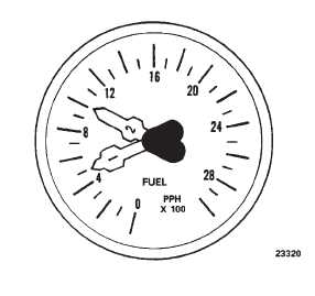
pounds per hour in 100 pound increments. The signal to
drive the indicator is derived from a fuel
Figure 2-4-5. Fuel Flow Indicator.
flow transmitter in the fuel line of each engine at the quick
disconnect shelf. Power to operate the No. 1 indicator is
from the No. 1 AC bus through the ENGINE NO. 1 FUEL
FLOW circuit breaker on the No. 1 DP. Power to operate
the No. 2 indicator is from the No. 2 AC bus through
ENGINE NO. 2 FUEL FLOW circuit breaker on the No.
2 PDP.
2-4-10. Pressure Refueling System.
The pressure refueling system permits rapid refueling of
all fuel tanks simultaneously or selective refueling of any
tank or combination of tanks. Maximum fueling rate is
300 gallons per minute at 55 psi. The system control
panel and refueling nozzle receptacle are on the right
side of the helicopter above the forward right landing
gear (fig. 2-4-6).
In addition to the control panel and refueling receptacle,
the system consists of dual fuel level control valve, a dual
fuel shutoff valve in each tank, a jet pump in each main
tank, and pressure refueling manifold.
a.
Dual Fuel Level Control Valves and Dual Fuel
Shutoff Valves. The dual fuel level control valves control
the operation of the fuel fuel shutoff valves. When fuel in
a tank rises to the full level during pressure refueling, the
floats in the control valve close and apply a signal to the
shutoff valve, closing it. the floats can also be closed
electrically to stop fuel flow into a tank at some intermedi-
ate level. The floats are controlled by the FUEL CELL
SHUTOFF VALVE TEST switches on the refueling con-
trol panel.
b.
Jet Pumps. The jet pump installed in each main
tank evacuates the refueling manifold and discharges
the displaced fuel into the main tank. The jet pump is
activated when the forward boost pump in each main
rank is first turned ON following pressure refueling.
c.
Pressure Refueling Manifold. The pressure re-
fueling manifold connects to all tanks to the pressure
refueling receptacle. It does not include projectile resist-
ant features because the fuel is evacuated before flight
by the jet pumps.
Electrical power is applied to the system only when the
REFUEL STA switch on the cockpit FUEL CONTR panel
is placed to ON. Power to operate the pressure refueling
system is supplied by the DC switched battery bus
through the REFUEL circuit breaker on the No. 1 PDP.
2-4-11. Controls and Indicators.
Except for the REFUEL STA switch on the cockpit FUEL
CONTR panel, all pressure refueling system controls
and indicators are on the pressure refueling station panel
(fig. 2-4-6).
2-4-12. PWR Control Switch.
The PWR (power) control switch is labeled ON and OFF.
When placed to ON, electrical power is applied to the
pressure refueling system and to the refueling station
quantity indicator provided the REFUEL STA switch on
the cockpit FUEL CONTR panel is at ON. Also, the PWR
ON light will illuminate, the fuel quantity indicator will
register the quantity of fuel in the tanks, and the REFUEL
VALVE POSN lights will illuminate momentarily. When
placed to OFF, electrical power is removed.
2-4-13. REFUEL STA Switch.
The REFUEL STA switch is on the cockpit FUEL CONTR
panel (fig. 2-4-1) when placed to ON, applies electrical
power from the DC switched battery bus to the PWR ON
switch on the refueling station panel. Setting the switch
to OFF after pressure refueling, closes the refuel valves
and discontinues electrical power to the refueling panel.
When pressure refueling, be sure the switch is at ON at
all times. If the switch is at OFF, the aft auxiliary tanks will
not fill, the remaining four tanks will fill to maximum, the
refuel station quantity indicator is inoperative, and there
is no precheck capability.
2-4-14. Fuel Quantity Indicator and Selector
Switch.
The pressure refueling station fuel quantity indicator and
selector switch (fig. 2-4-4) are identical to those in the
cockpit. The indicator at the refueling station indicates
fuel quantity only when the REFUEL STA switch on the
cockpit FUEL CONTR panel (fig. 2-4-1) is at ON and the
PWR switch on the refueling station panel (fig. 2-4-6) is
at PWR ON. Electrical power to drive the indicator is AC
from a solid-state inverter in the cabin at sta 220. The
inverter, in turn, is powered by the DC switched battery
bus through the FUEL REFUEL circuit breaker on the No.
1 PDP.
2-4-15. FUEL
CELL
SHUTOFF
VALVE
TEST
Switches.
Seven three-position FUEL CELL SHUTOFF VALVE
TEST switches are on the refueling control panel (fig.