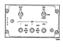
TM 1-1520-240-102-11-2 When the switches are ON, the respective main relayoperates, which energizes and connects the generator tothe buses. At OFF RESET, the generator is deenergizedand disconnected from the bus. This position is also usedto reset a generator. The TEST position is provided toallow the generator to be energized but disconnectedfrom the bus to determine whether the AC produced is ofproper frequency and voltage, except the APU genera-tor.Figure 2-11-2. Electrical Power Panel2-11-4. GEN OFF Cautions.Two generator caution capsules labeled 712 NO. 1GEN OFF and NO. 2 GEN OFF, 714A GEN 1 AND GEN2 are on the master caution/advisory panel ( 712 fig.2-14-5 714A fig. 2-14-6).These caution capsules illumi-nate whenever the generators are in operative.The cap-sules are controlled by the main generator contactorswhen the generator control switches are in either ON orOFF RESET.In TEST, the capsules are controlled by thegenerator control switch and will extinguish if generatoroutput has the proper frequency and voltage.Power tooperate the generator capsules is supplied by the DCessential bus through the LIGHTING CAUTION PNL cir-cuit breakers on the No. 1 PDP.2-11-5. EXT PWR Caution.CAUTIONWhen external power is used, a visualcheck shall be made by the crew to ensurethat the external power unit has been dis-connected from the helicopter before taxi-ing.An external power caution capsule labeled EXT PWR ison the master caution panel (fig. 2-14-5 and fig.2-14-6).This capsule illuminates and remains illuminatedwhenever external power is connected.The light is con-trolled by the AC external power contactor and the DCpower relay.The capsule extinguishes when the genera-tors are supplying current to the buses.Power to operatethe external power caution capsule is supplied by the DCessential bus through the LIGHTING CAUTION PNL cir-cuit breaker on the No. 1 PDP.2-11-6. DC System.The direct current (DC) power supply system supplies28-volt DC from the No. 1 transformer rectifier (RECT) toNo. 1 DC bus and the No. 2 RECT supplies power to theNo. 2 DC bus (fig. FO-4 and FO-7).RECT convert 200VAC power to 28-volt DC power for use in the DC distribu-tion system.Cooling air for the RECTS is obtained from within thecabin.The air inlets are located at sta. 176 on the left andright side of the cabin behind the troop seats.If the inletsare blocked, the RECTS will overheat.A bus-tie relay is between No. 1 and No. 2 DC buses.Ifeither RECT fails, the respective RECT failure relay op-erates and the bus-tie relay closes automatically to con-nect the unpowered bus to operating RECT.In addition toNo. 1 and No. 2 DC buses, the DC system includes anessential bus, a switched battery bus, and a hot batterybus.During normal operation, the essential bus and theswitched battery bus are energized by No. 1 DC bus.Ifboth DC buses fail or if NO. 1 DC bus fails and does notbus-tie to No. 2 DC bus, the essential bus, the switchedbattery bus, and the hot battery bus will be energized bythe battery as long as the BATT switch is ON.Thesebuses provide power to emergency, ground mainte-nance, and communications components.The hot bat-tery bus and switched battery bus are energized as longas the battery is connected.The hydraulic reservoir levelindicators and the emergency APU control circuits andcabin and maintenance lights are on these buses.The 24-volt nickle cadmium battery is located in the leftforward electrical compartment.The battery capacity is11 ampere-hours.A battery charger is connected to thebattery.The battery charger receives power from No. 1AC bus, rectifies the AC and applies the DC to the batteryto maintain a charge on the battery.Sensors in the battery charger detect battery or batterycharger overtemperature, short or open circuits or cellimbalance.If any of these conditions occur, the batterycharger will stop functioning and activates the BATT SYSMAL caution capsule on the master caution panel.External DC power is supplied to the DC buses of thehelicopter by connecting the external DC power sourceto the DC external power receptacle (fig. 2-11-1).Applica-tion of external power operates the DC external powerrelay which connects the power source to No. 1 DCbus.No. 2 bus is energized when the bus tie relay opera-tes.If the polarity of the external power is reversed, ablocking diode in the circuit prevents the external powerrelay from closing.
Integrated Publishing, Inc. - A (SDVOSB) Service Disabled Veteran Owned Small Business