TM 55-1520-240-T
4-2.3
ENGINE ANTI-ICING SYSTEM VISUAL CHECK
4-2.3
INITIAL SETUP
Equipment Condition:
Applicable Configurations:
TM 55-1520-240-23:
Without 43 land 74
Battery Disconnected
Tools:
Electrical Power Off
Aircraft Mechanic's Tool Kit,
Hydraulic Power Off
NSN 5180-00-323-4692
Engine Work Platforms Open
Materials:
Engine Access Covers Open
None
Engine Air Inlet Screens Removed
Engine Transmission Upper Fairings Opened
Personnel Required:
Medium Helicopter Repairer
References:
TM 55-1520-240-23
TASK
RESULT
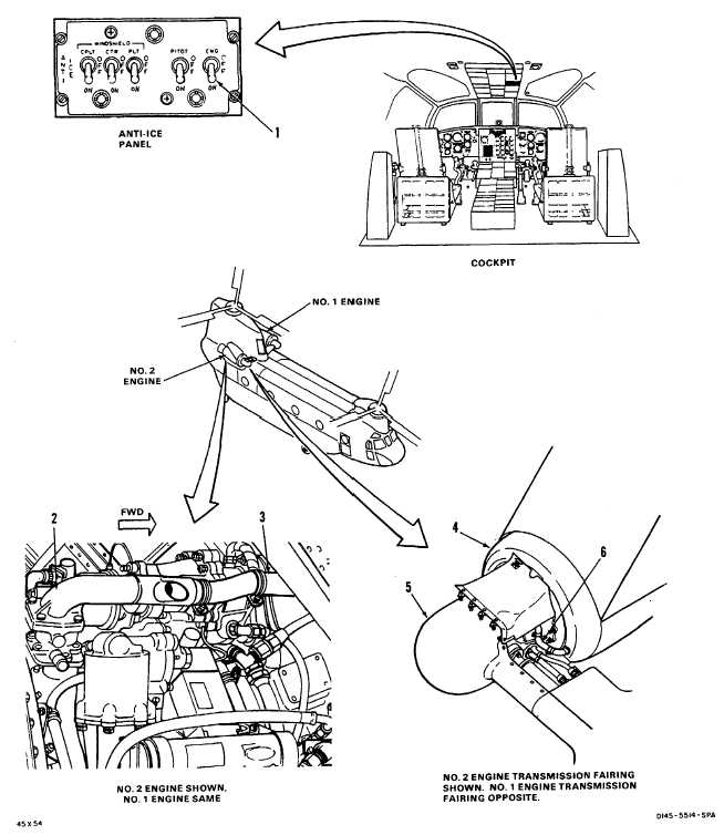
1. Check ENG anti-ice switch (1).
If switch (1) is loose or damaged, tighten or replace it as
required.
2. Check No. 1 engine anti-icing valve (2) and hose (3).
If valve (2) is loose or damaged, tighten or replace it as
required. If electrical connector or wiring to valve is
damaged, replace it. If hose (3) is loose or damaged,
tighten clamps or replace hose as required.
3. Check No. 1 engine air inlet fairing (4).
If fairing (4) is damaged, repair or replace it.
4. Check No. 1 engine transmission fairing (5) and hose
If fairing (5) is damaged, repair or replace it. If hose (6) is
(6).
loose or damaged, tighten or replace it as required.
5. Repeat steps 2 through 4 on No. 2 engine.
FOLLOW-ON MAINTENANCE:
TM 55-1520-240-23:
Close engine transmission upper fairings.
END OF TASK
4-34 Change 17