TM 1-1520-252-T
6-3.3 TRANSMISSION CHIP DETECTOR FUZZ BURN OFF OPERATIONAL CHECK
6 - 3 . 3
INITIAL SETUP
Personnel Required:
Aircraft Electrician
References:
TM 55-1520-240-23
Equipment Condition:
TM 55-1520-240-23:
Battery Connected
Electrical Power On
Applicable Configurations:
W i t h
Tools:
Test Set, Chip Detector Fuzz Burn Off
TE 145-02-5400-1 (Appx E, E-266)
Multimeter
Materials:
None
TASK
RESULT
1.
2.
3.
4.
5.
6.
7.
8.
9.
10.
11
12
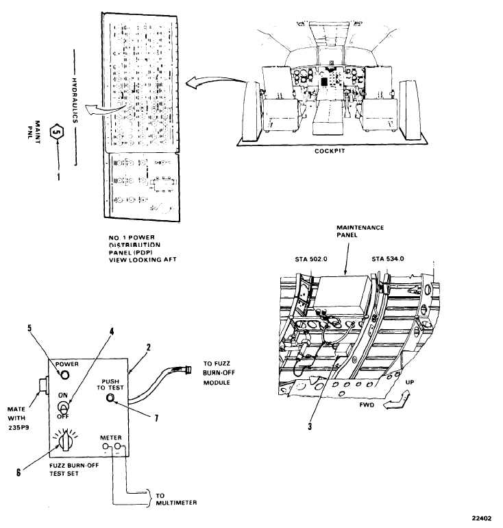
Disconnect plug 235P9 from fuzz burn-off
module.
Connect fuzz bum-off test set (2) to fuzz
burn-off module (3). Connect plug 235P9 to
fuzz burn-off test set.
Check That MAINT PNL circuit breaker (1) is
closed.
If MAINT PNL circuit breaker (1) is open, close it. If
it opens again, go to Task 8-14.4.
NOTE
When the fuzz burn off test set is plugged
in, the latch TEST/RESET switch is dis-
abled.
Connect multimeter to fuzz bum-off test set
(2). Adjust multimeter to 50VDC scale.
Turn test set ON/OFF switch (4) to ON.
Test set POWER light (5) shall come on. If it does
not, go to Task 6-3.4.
Multimeter shall read above 24VDC. If it does not,
repair or replace test set as required.
Multimeter reading shall drop below 14VDC and
return to original reading. If it does not, repair or
replace fuzz burn off module (3) as required.
Verify that corresponding latch indicator trips
(black/white).
Results should be the same for steps 6 and 7 at
each selector switch position on the test set.
Adjust fuzz burn-off test set selector switch
(6) to FWD XMSN.
Press and release fuzz burn-off test set TEST
switch (7).
Repeat steps 6 end 7 for each selector switch
position on fuzz burn-off test set.
NOTE
Wait at least seven seconds before re-
peating test on any one selector switch
position.
Turn test set ON/OFF switch (4) to OFF. Open
MAINT PNL circuit breaker (1). Disconnect
multimeter from fuzz burn-off test set (2).
Disconnect fuzz burn-off test set. Connect
plug 235P9 to fuzz burn-off module (3).
Close MAINT PNL circuit breaker (1).
Set GND RESET/TEST switch on maintenance
panel at sta 516 to RESET.
Indicator reset (black/white).
FOLLOW-ON MAINTENANCE:
TM 55-1520-240-23:
Battery disconnected.
Electrical power off.
6-88
Change 12
END OF TASK