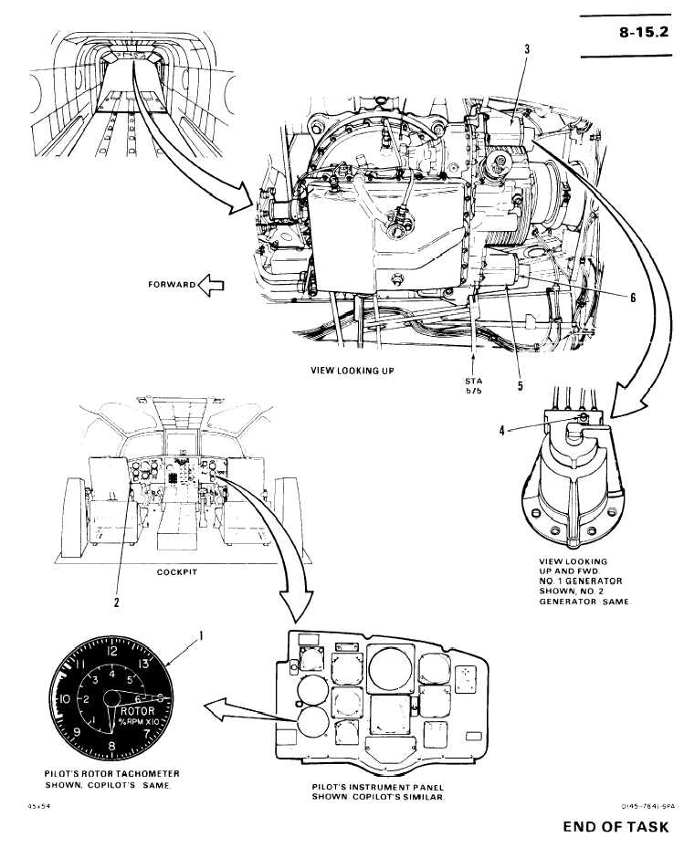
TM 55-1520-240-T8-15.2 ROTOR TACHOMETER VISUAL CHECKINITIAL SETUPApplicable Configurations:AllTools:Electrical Repairer’s Tool Kit,N S N 5 1 8 0 - 0 0 - 3 2 3 - 4 9 15Materials:NonePersonnel Required:68F10 Aircraft ElectricianReferences:T M 5 5 - 1 5 2 0 - 2 4 0 - 23Equipment Condition:T M 5 5 - 1 5 2 0 - 2 4 0 - 2 3:Battery DisconnectedElectrical Power OffHydraulic Power OffLeft and Right BafflesOpen Under Aft TransmissionT A S KR E S U LT1. Check pilot’s rotor tachometer indicatorIf tachometer (1 ) is loose or damaged, tighten or(1).replace it as required.2. Check copilot’s rotor tachometer indica-If tachometer (2) is loose or damaged, tighten ortor (2).replace it as required.3. Check No. 1 generator (3).If plug (4) is loose or damaged or wiring to plug isdamaged, tighten or repair it as required.4. Check No. 2 generator (5).If plug (6) is loose or damaged or wiring to plug isdamaged, tighten or repair it as required.FOLLOW-ON MAINTENANCE:Left and right baffles closed under aft trans-mission.8-335
Integrated Publishing, Inc. - A (SDVOSB) Service Disabled Veteran Owned Small Business