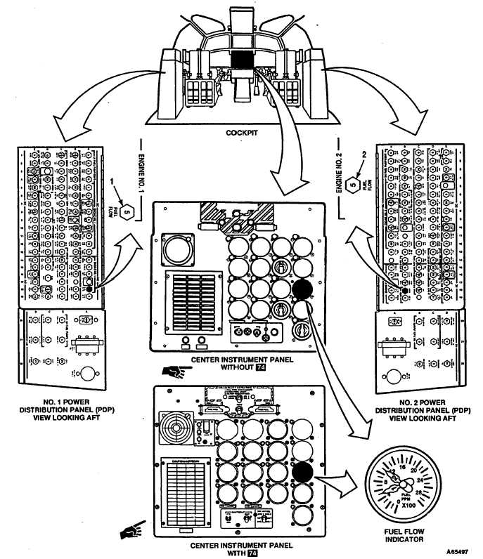
TM 55-1520-240-T8-16.3 ENGINE FUEL FLOW INDICATING SYSTEM OPERATIONAL CHECK8-16.3INITIAL SETUPReferences:Applicable Configurations:TM 55-1520-240-10AllTM 55-1520-240-23Tools:Equipment Condition:NoneTM 55-1520-240-23:Materials:Battery ConnectedNoneElectrical Power OnPersonnel Required:Hydraulic Power OffArmy Rotary Wing Aviator (2) Engine Fuel Flow Indicating System Visual CheckAircraft ElectricianCompleted (Task 8-16.2)TASKRESULT1.Checkthat ENGINE NO. 1 FUEL FLOW circuit breakerIf circuit breaker (1) is open, close it. If it opens again, go(1)is closed.to task 8-16.4.2.Checkthat ENGINE NO. 2 FUEL FLOW circuit breakerIf circuit breaker (2) is open, close it. If it opens again, go(2)is closed.to task 8-16.5.3.Have pilot start engines and stabilize rotors at groundIndicator readings shall be approximately the same asidle and minimum beep. Observe fuel flow indicator (3)indicated by IDLE FUEL FLOW chart. If No. 1 pointerand compare readings with IDLE FUEL FLOW chart.does not indicate any fuel flow, go to task 8-16.6. If No. 1(Ref TM 55-1520-240-10.)pointer does not indicate approximate fuel flow, go totask 8-16.7. If No. 2 pointer does not indicate any fuelflow, go to task 8-16.8. If No. 2 pointer does not indicateapproximate fuel flow, go to task 8-16.9.FOLLOW-ON MAINTENANCE:TM 55-1520-240-23:Shut down engines.Battery disconnected.Electrical power off.Hydraulic power off.END OF TASKChange 19 8-347
Integrated Publishing, Inc. - A (SDVOSB) Service Disabled Veteran Owned Small Business