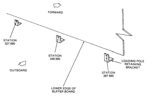
TM 55-1680-358-12&P2-7. Aircraft Preparation. Prepare the aircraft for safeground maintenance as follows:a. Cleaning. Before attempting to install theHelicopter Internal Cargo Handling System, the floor ofthe aircraft should be cleaned of all dirt and debris.b. Preparation. After the floor has been cleaned,proceed as follows:NOTELoading pole ground able is secured toretaining brackets. Detach the groundcable to aircraft in or near the samelocation.CAUTIONEnsure loading pole grounding cable isoutboard of outboard rail/rollerassembly, stations 272.531 to 374.000(3 and 4, Figure 3-2) at installation.(1) Remove loading pole retaining bracketslocated at stations 327.680, 348.980 and 387.680 onright-hand side of aircraft (Figure 2-1) and discardbrackets.(2) Remove the aircraft ramp extensionsfrom the ramp. Locate the master drill fixture, Part No. B18049 140-MDF, over one of the ramp extensions, asshown in Figure 2-2. Make sure the alignment pins aresnug against the ramp extension. Use at least two C-clamps to hold the fixture in position.CAUTIONDrilled holes must be within tolerance,clean and free of burrs to ensure properengagement of pins.(3) Drill first two holes (0.396 to 0.403 inchdiameter). Drill one at each end, using the fixture drillguide holes (Figure 2-2).(4) Repeat steps 2 and 3 for remaining rampextension.Figure 2-1. Loading Pole Retaining Bracket Locations2-4
Integrated Publishing, Inc. - A (SDVOSB) Service Disabled Veteran Owned Small Business