TM 1-1520-240-10
2-1-5
The switch positions are arranged so the power steering
system cannot be energized and used with swivel locks
engaged. The aft right landing gear is hydraulically steer-
able and electrically controlled by the steering control
knob.
The PWR STEER caution capsule on the master caution
panel indicates that power steering circuits have failed or
the aft right wheel has exceeded turning limits. These
limits are set at 58_ for a left turn and 82_ for a right turn.
If turning limits are exceeded, an out-of-phase switch on
the landing gear automatically closes the power steering
solenoid valve, lights the caution capsule, and removes
electrical power from the control box. To reenergize the
power steering system, the landing gear must be re-
turned within operating limits and the SWIVEL switch
must be recycled.
Hydraulic power to operate the power steering actuator
and the swivel locks is supplied by the utility hydraulic
system through the utility system pressure control mod-
ule and separate power steering and swivel lock module.
Electrical power to control the steering and swivel locks
system is supplied by the No. 1 DC bus through the
BRAKE STEER circuit breaker on the No. 1 PDP.
2-1-6. STEERING CONTROL Panel.
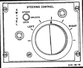
The STEERING CONTROL panel (fig. 2-1-4) is on the aft
end of the console. It contains the SWIVEL switch, the
steering control knob, a fail-safe module and relay, and
a servoamplifier. The fail-safe module monitors the
steering electrical circuits. A malfunction which could
cause a steering hardover will be detected by the fail-
safe module and the relay which disables the system and
turns on the PWR STEER caution light.
a.
SWIVEL switch. A three-position switch labeled
STEER, UNLOCK, and LOCK. Setting the switch to
STEER applies DC power to the circuits in the power
steering control box and arms the power steering actua-
tor. Rotating the steering control knob will activate the
power steering actuator and the aft wheel will
Figure 2-1-4. Steering Control Panel
swivel. Setting the SWIVEL switch to UNLOCK deener-
gizes the power steering circuits in the control box and
the power steering actuator. It maintains the swivel locks
in the disengage position and both aft wheels are free to
swivel. Setting the SWIVEL switch to LOCK energizes
the swivel lock and centering cam control valve. Utility
system pressure is directed to the lock port of the swivel
lock cylinder and centering cam. The aft wheels will ro-
tate to neutral trail position and the swivel lock will en-
gage when the helicopter weight is lifted from the rear
wheels. AFCS heading hold is disabled at STEER and
UNLOCK.
b.
Steering control knob. The steering control knob
has index marks around the knob to indicate degrees of
knob rotation LEFT and RIGHT in increments of 30_.
These index marks do not represent wheel turn angle;
they are reference marks only. The knob is spring-loaded
to zero turn angle. Power steering is accomplished by
rotating the knob a given amount in the desired direction.
When the knob is rotated, a servo valve on the power
steering actuator regulates hydraulic pressure to extend
or retract the actuator. A feedback variable resistor, also
on the power steering actuator, stops actuator travel
when the selected turn radius is reached.
2-1-7. Brake System.
The four wheels of the forward landing gear, and two
wheels of the aft landing gear, are equipped with self–ad-
justing disk brakes. Both forward and aft brakes can be
applied and brake pressure maintained by depressing
the pedals. Hydraulic pressure is supplied by utility hy-
draulic system.
2-1-8. Brake Pedals.
When either the pilot’s or copilot’s brake pedals are
pressed, pressure from the master brake cylinders goes
to a transfer valve in the brake lines. This allows indepen-
dent braking by either pilot. From these transfer valves,
pressure is directed through a parking brake valve to the
forward and aft wheel brakes.
2-1-9. Parking Brake Handle.
A parking brake handle (4, fig. 2-1-3) is at the bottom left
corner of the pilot’s section of the instrument panel. The
brake handle is mechanically connected to the parking
brake valve. The parking brake valve is electrically con-
nected to the PARK BRAKE ON caution capsule on the
master caution panel. When the brake pedals are
pressed and the parking brake handle is pulled OUT,
pressure is trapped and maintained on forward and aft
wheel brakes. At the same time, electrical power from the
DC essential bus through the LIGHTING CAUTION PNL
circuit breaker, lights the PARK BRAKE ON caution cap-
sule.
The parking brakes must be released by applying pres-
sure to the brake pedals. This action automatically opens
the parking brake valve, retracts the parking brake han-
dle, and extinguishes the PARK BRAKE ON caution cap-
sule.