TM 1-1520-240-10
9-1-28
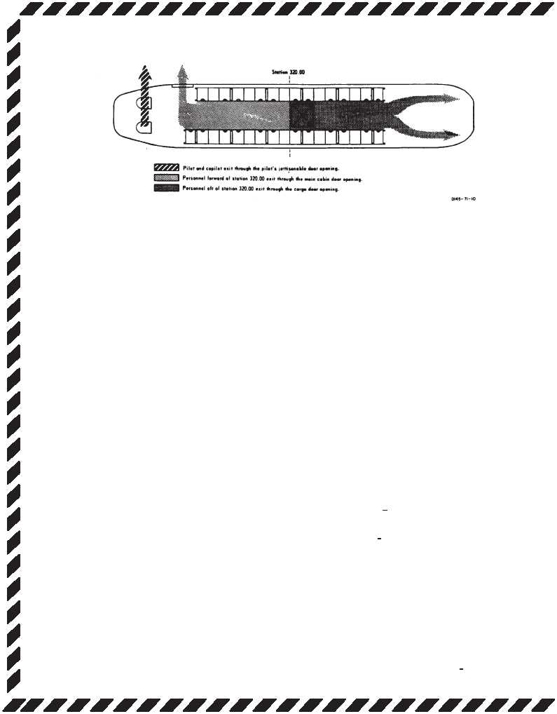
Figure 9-1-9. Ditching Exits
9-1-73. Flight Controls.
9-1-74. Longitudinal Cyclic Trim (LCT) System
Failure.
Should the system fail during cruise, with the cyclic trim
system programmed for maximum forward tilt of the ro-
tors, an abnormal nose-up attitude will result with de-
creasing airspeed. Should one or both cyclic actuators
fail in full retract position, airspeed must be limited ac-
cording to Vne for retracted longitudinal cyclic trim. With
both LCTs partially or fully retracted, maintain below Vne
and if failure occurs extended, maintain airspeed at or
above 60 KIAS or until the approach to landing. Should
the longitudinal cyclic trim system fail, perform the follow-
ing:
CYCLIC TRIM circuit breakers — In. If cyclic trim opera-
tion is not restored, proceed with the procedures below
for AUTO or MANUAL modes of operation.
If in AUTO mode:
1. Airspeed — Adjust.
2. CYCLIC TRIM switch — MANUAl.
3. FWD and AFT CYCLIC TRIM switches —
Adjust for airspeed.
If LCT operation is not indicated:
FWD and AFT CYCLIC TRIM switches — RET for 30
seconds, before landing.
If in MANUAL mode:
1. Airspeed — Adjust.
2. CYCLIC TRIM switch — AUTO.
If normal LCT operation is not indicated:
1. CYCLIC TRIM switch — MANUAl.
2. FWD and AFT CYCLIC TRIM switches —
RET both LCTS for 30 seconds, before land-
ing.
If both actuators are retracted, the landing will be normal.
If one or both actuators fail in extended position, the pitch
atitude of the helicopter will be higher than normal during
the approach and will be dependent upon the amount of
actuator extension at the time of the failure. Execute a
shallow approach to a hover or to the ground with a
normal touchdown, avoiding large cyclic changes. When
the aft gear areon the ground, apply brakes and lower the
nose. As the forward gear touch the ground, the aircraft
will tend to accelerate more than normal.Continue to ap-
ply brakes as necessary to prevent forward movement.
If the helicopter is taxied with the actuators failed in the
extend position, use minimum control applications and
adjust the thrust control at ground detent or higher. There
is an increased susceptibility to droop-stop pounding
with this condition.
9-1-75. Single AFCS Failure — Both Selected.
A malfunction of the AFCS can usually be detected by an
abrubt attitude change (hardover) or unusual oscilations
in one or more of the flight control axes or by lighting of
the NO.1 or NO. 2 AFCS OFF caution. If flight is con-
ducted at low altitude such as contour or NOE, a climb to
higher altitude must be iniated before the pilot attempts
isolation of the defective system.
1. Airspeed — Reduce to 100 KIAS or Vne,
whichever is slower.
2. Altitude — Adjust as required.
NOTE
A hardover in the opposite direction may oc-
cur when the malfunctioning AFCS is turned
off and the functioning AFCS reacts on the
flight controls.
3. AFCS SYSTEM SEL switch
— Isolate
defective system. Turn NO. 1 ON, if not
isolated, turn NO. 2 ON.
If system is not isolated:
AFCS SYSTEM SEL switch — OFF.


