TM 1-1520-240-BD
(4)
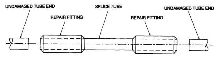
Insert a repair fitting on each end of the
splice tube, and place the splice tube between the
undamaged ends of the tube, Figure 7-7.
(5)
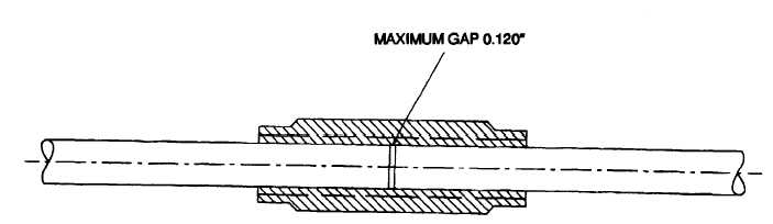
Slide the repair fittings o that they overlap
on both the undamaged ends and the splice tube. The
undamaged end and the splice tube should be butted up
to each other at the mid potion of the repair fitting (use
test coupling in BDR kit), Figure 7-8.
(6)
Press the undamaged tube ends firmly
against the splice tube and use the heat gun to blow hot
air over the repair fitting. This will cause the fitting to
shrink down on the tube ends.
(7)
Record BDAR action taken.
Figure 7-7. Splice Repair Assembly
Figure 7-8. Repair Fitting and Tube installation
7-9