TM 55-1520-240-T
TM 55-1520-240-T
4-2.4
ENGINE ANTI-ICING SYSTEM OPERATIONAL CHECK
4-2.4
INITIAL SETUP
References:
Applicable Configurations:
TM 55-1520-240-23
Without 43 and 74
Equipment Condition:
Tools:
TM 55-1520-240-23:
None
Battery Connected
Materials:
Electrical Power On
None
Hydraulic Power Off
Visual Check of Engine Anti-Icing System Performed
Personnel Required:
(Task 4-2.3)
Medium Helicopter Repairer
Aircraft Electrician
TASK
RESULT
1.
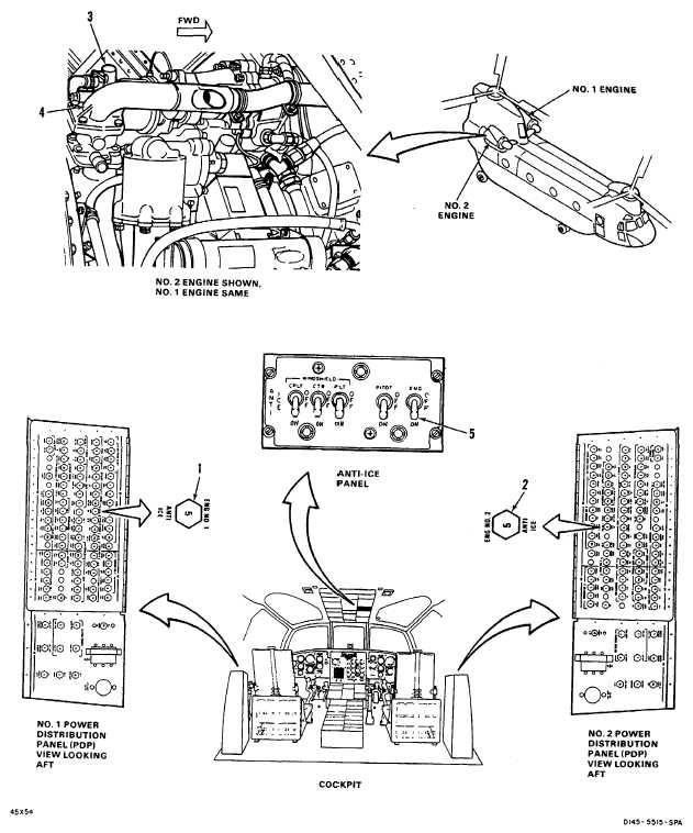
Check that ENG NO. 1 ANTI ICE circuit breaker (1) is
If ENG NO. 1 ANTI ICE circuit breaker (1) is open, close
closed.
it. If it opens again, go to task 4-2.5.
2.
Check that ENG NO. 2 ANTI ICE circuit breaker (2) is
If ENG NO. 2 ANTI ICE circuit breaker (2) is open, close
closed.
it. If it opens again, go to task 4-2.5.
WARNING
Engine anti-ice valve solenoid is energized
when ENG anti-ice switch is at OFF. Solenoid
body temperature may exceed 300°F (149°C).
Contact with solenoid body could cause per-
sonnel burns or could be an ignition source.
3.
Listen to solenoid (3) on No. 1 engine anti-ice valve
No. 1 engine anti-icing valve solenoid (3) shall click when
(4). Move ENG anti-ice switch (5) from OFF to ON to
switch (5) is cycled. If it does not, go to task 4-2.6.
OFF.
4.
Listen to solenoid (3) on No. 2 engine anti-ice valve
No. 2 engine anti-icing valve solenoid (3) shall click when
(4). Move ENG anti-ice switch (5) from OFF to ON to
switch (5) is cycled. If it does not, go to task 4-2.7.
OFF.
NOTE
If system was reported inoperative and operational
check found no problem, have pilot recheck system.
If system fails pilot's check again, replace
appropriate anti-icing valve.
FOLLOW-ON MAINTENANCE:
TM 55-1520-240-23:
Electrical power off.
Battery disconnected.
Engine access covers closed.
Engine work platforms closed.
Engine air inlet screens installed.
END OF TASK
Change 17 4-35


