TM 55-1520-240-T
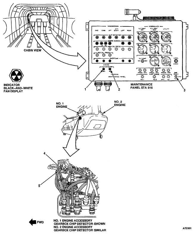
4-13.2 ENGINE ACCESSORY GEARBOX CHIP DETECTORS VISUAL CHECK
4-13.2
INITIAL SETUP
Applicable Configurations:
References:
With 74
TM 55-1520-240-23
Tools:
Equipment Condition:
Aircraft Mechanic's Tool Kit,
TM 55-1520-240-23:
NSN 5180-00-323-4692
Battery Disconnected
Materials:
Electrical Power Off
None
Hydraulic Power Off
Personnel Required:
No. 1 or No. 2 Engine Work Platform and Access
Medium Helicopter Repairer
Doors Open
TASK
RESULT
1.
Check NO.1 and NO.2 ENGINE CHIP DETECTOR
If either indicator (1 or 2) is loose or damaged, tighten or
indicators (1 and 2).
replace it as required. If either indicator displays black-
and-white fan, go to task 4-13.4.
2.
Check GND switch (3).
If switch (3) is loose or damaged, tighten or replace it as
required.
CHECK NO. 1 ENGINE
3.
Check No.1 engine accessory gearbox chip detector
If chip detector (4) is loose or damaged, tighten or replace
(4).
it as required. If wire (5) is loose or damaged, tighten
connection, repair, or replace engine to airframe harness
as required.
CHECK NO. 2 ENGINE
4.
Check No.2 engine accessory gearbox chip detector
If chip detector (4) is loose or damaged, tighten or replace
(4).
it as required. If wire (5) is loose or damaged, tighten
connection, repair, or replace engine to airframe harness
as required.
FOLLOW-ON MAINTENANCE:
None
END OF TASK
Change 17 4-315