8-8.3
TM 55-1520-240-T
8 - 8 . 3 H Y D R A U L I C O I L T E M P E R A T U R E I N D I C A T I N G S Y S T EM
O P E R A T I O N A L C H E C K
Personnel Required:
INITIAL SETUP
67U10 Medium Helicopter Repairer
67U20 Medium Helicopter Repairer
Applicable Configurations:
All
References:
TM 55-1520-240-23
Tools:
None
Equipment Conditions:
TM 55-1520-240-23:
Materials:
Battery Connected
None
Electrical Power On
Hydraulic Power On
Hydraulic Oil Temperature Indicating System
Visual Check Performed (Task 8-8.2)
TASK
RESULT
1.
2.
3.
4.
5.
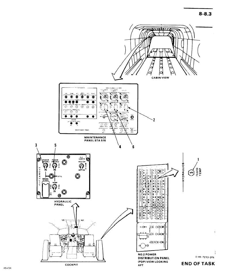
Check that HYDRAULICS FLUID TEMP
circuit breaker (1) is closed.
Check UTILITY HYDRAULICS
TEMPERATURE indicator (2).
Set POWER XFR NO. 1 switch (3) to
ON. Check NO. 1 FLT CONT HY-
DRAULICS temperature indicator (4).
Set POWER XFR NO. 1 switch (3) to
OFF.
Set POWER XFR NO. 2 switch (5) to
ON. Check NO. 2 FLT CONT HY-
DRAULICS TEMPERATURE indicator
(6).
6. Set POWER XFR NO. 2 switch (5) to OFF.
If circuit breaker (1) is open, close it. If it opens
again, go to task 8-8.4.
Pointer on indicator (2) shall move upscale as fluid
temperature increases. Temperature indication
shall not exceed 120°C. If indicator pointer does
not move upscale or pointer exceeds 120°C, go to
task 8-8.5.
Pointer on indicator (4) shall move upscale as fluid
temperature increases. Temperature indication
shall not exceed 120°C. If indicator pointer does
not move upscale or pointer exceeds 120°C, go to
task 8-8.6.
Pointer on indicator (6) shall move upscale as fluid
temperature increases. Temperature indication
shall not exceed 120°C. If indicator pointer does
not move upscale or pointer exceeds 120°C, go to
task 8-8.7.
FOLLOW-ON MAINTENANCE:
TM 55-1520-240-23:
Battery Disconnected
Electrical Power Off
Hydraulic Power Off
8 - 1 38


