TM 55-1520-240-T
8-13.3 TURN AND SLIP INDICATORS OPERATIONAL CHECK
8-13.3
INITIAL SETUP
Applicable Configurations:
All
Tools:
Inclinometer
Materials:
None
Equipment Condition:
TM 55-1520-240-23:
Battery Connected
Electrical Power On
Hydraulic Power Off
Visual Check of Turn and Slip Indicators Performed
Personnel Required:
Aircraft Electrician
References:
TM 55-1520-240-23
(Task 8-13.2)
TASK
RESULT
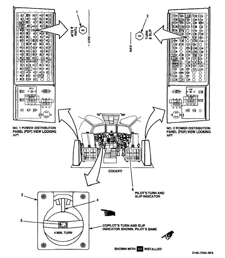
1.
Check that NAV TURN & SLIP circuit breaker (1) is
closed.
2.
Check that NAV TURN & SLIP ClRCUlT BREAKER (2)
is closed.
3.
Check copilot’s turn and slip indicator (3).
If circuit breaker (1) is open, close it. If it opens again, go
to task 8-13.4.
If circuit breaker (2) is open, close it. If it opens again, go
task 8-13.4.
If pointer (4) is not centered, replace indicator (3). If ball
(5) is not centered, use inclinometer to verify ball position.
If ball position does not agree with inclinometer, replace
indicator.
4.
Repeat step 3 for pilot’s turn and slip indicator (6).
Then, go to step 5.
5.
On next flight, have pilots check operation of their
turn and slip indicators.
Pointer (4) on indicators (3 and 6) shall move in direction
of turn, If it does not, go to task 8-13.5.
FOLLOW-ON MAINTENANCE:
TM 55-1520-240-23:
Battery disconnected.
Electrical power off.
END OF TASK
8-312
Change 17
Page 8-313 is intentionally left blank