TM 1-1520-240-10
6-6-14
6-6-21. Winch.
Refer to Chapter 4, Section III.
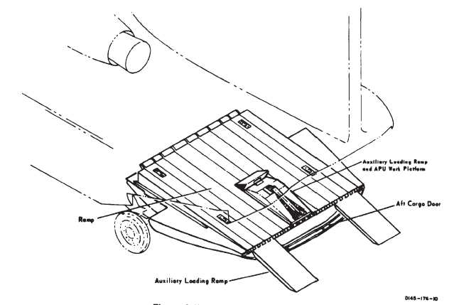
6-6-22. Cargo Door and Ramp.
The cargo door and ramp has an upper section, or cargo
door, and lower section, or ramp. The door retracts into
the ramp when the ramp is being lowered and extends
when the ramp is being raised. Retraction or extension
of the door can be isolated through the ramp sequence
valve so the ramp can be raised or lowered with the door
retracted into the ramp or extended. The door is an inte-
gral part of the ramp and only provides closure; therefore,
references made to the ramp will be understood to in-
clude the door and its related movements. The cargo
door is jettisonable to provide an emergency exit. The
cargo door and ramp is located at the aft end of the cargo
compartment and is used for troop and cargo loading and
unloading. In closed position, it conforms to the side con-
tours of the fuselage (fig. 6-6-7). Internal locks in the
ramp actuating cylinders prevent accidental opening and
constitute the only locking mechanism for keeping the
ramp closed. The ramp is hinged to the fuselage and
opens rearward and downward to rest on the ground.
When lowered to ground rest, the ramp inclines down-
ward approximately 6.75_ and maintains a uniform
78-inch overhead clearance, (if HICHS is not installed),
of the cargo compartment. A continuous hinge runs the
entire width of the aft upper edge of the ramp and holds
the three auxiliary loading ramps. The auxiliary ramps
unfold to bridge the gap between the ramp and the
ground for vehicle loading and unloading. they can be
adjusted laterally to accommodate various vehicle
thread widths. Hydraulic power to operate the ramp is
supplied through the utility hydraulic system.
6-6-23. RAMP CONTROL Valve.
Lowering and raising the ramp is controlled by a RAMP
CONTROL valve on the right side of the aft cargo
compartment between the floor and the overhead at sta
490 (fig. 6-6-8). The RAMP CONTROL valve is operated
either electrically or manually. Electrical operation is per-
formed by setting the RAMP PWR switch to EMERG, and
using the RAMP EMER control switch on the cockpit
overhead HYD control panel (Chapter 2, Section VI).
Manual operation is accomplished by setting the RAMP
PWR switch to ON, and using a three-position lever
mounted on the RAMP CONTROL valve. the lever posi-
tions are labeled UP, STOP, and DN (down). The control
lever can be reached from the outside through a hinged
panel on the aft fuselage.
Figure 6-6-7. Cargo Door and Ramp