TM 1-1520-240-10
6-6-16
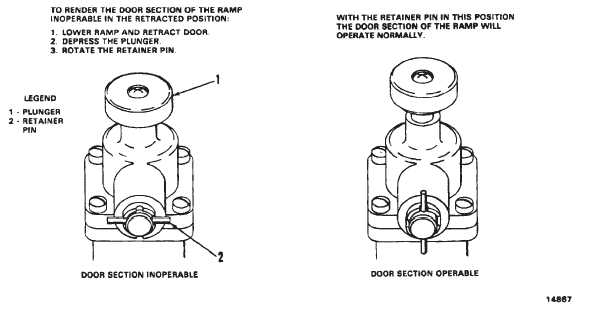
CAUTION
Do not press the sequence valve plunger
unless the ramp is down.
6-6-24. Ramp Control Sequence Valve.
A mechanically operated sequence valve controls the
sequence of the cargo door and ramp operation (fig.
6-6-9). The valve is below the ramp control valve at the
ramp hinge line. A plunger on the top of the valve is
manually pressed to hold the cargo door at full open
during ramp operation. The plunger can be locked in the
depressed position by rotating a retainer pin which ex-
tends from the side of the valve.
6-6-25. Pressure Actuated VAlve.
Ramp operation is stopped during cargo door operation
by a hydraulic pressure actuated valve. The valve is
locked near the ramp control valve (fig. 6-6-8). A plunger
provides manual override of the valve if it sticks.
6-6-26. Accumulator Gage.
A gage at station 534, right side indicates APU accumu-
lator pressure in psi (fig. 6-6-8). A pressure reading on
the accumulator gage in excess of 2,500 psi is sufficient
for operating the ramp.
6-6-27. Equipment Loading and Unloading.
The following procedures should be observed in prepar-
ing the helicopter for cargo transport mission:
a.
Doors — Open.
b.
Parking brake — ON.
c.
Troop seats — Stow.
d.
Cargo compartment — Clean.
e.
Tiedown devises — Check, for type and quanti-
ty.
f.
10,000 lb tiedown fittings — Install as required.
g.
Loading aids — Check, for condition and opera-
tion.
h.
Weight and balance data — Check.
i.
Emergency equipment — Check.
j.
Emergency exits — Inspect.
k.
Cargo load — Inspect.
6-6-28. Ramp Operation.
6-6-29. Normal Operation.
WARNING
When the RAMP PWR switch is OFF, be
sure the RAMP CONTROL VALVE remains
at STOP. If the RAMP CONTROL VALVE is
moved to UP or DN, the ramp may free fall.
1. Lower the ramp as follows:
a. RAMP PWR switch — ON.
NOTE
Perform step b. and c. only if the ramp is low-
ered with accumulator pressure.
b. APU accumulator gage — Check 2,500
psi or more. If pressure reading is below
2,500 psi, operate the hand pump to
build up pressure.
c. EMERG UTIL PRESS valve — Open.
Figure 6-6-9. Sequence Valve Operation