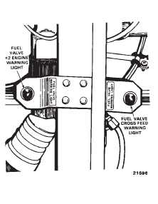
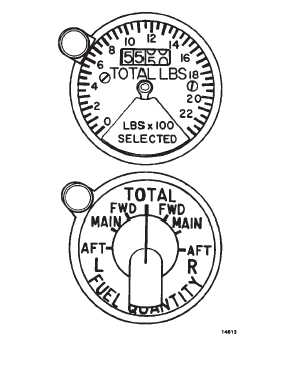
TM 1-1520-240-102-4-32-4-6. Manual Defueling Valve.A manual defueling valve is in the aft cargo compartmentnext to FUEL VALVE # 2 ENGINE. The valve should onlybe used by maintenance personnel to defuel the helicop-ter or adjust fuel load.2-4-7. Fuel Quantity Indicator and Selector.An indicator calibrated to measure fuel quantity inpounds and seven position selector switch (fig. 2-4-4) ison the center instrument panel. Power is supplied to theindicator through the FUEL QUANTITY selector switchby the No. 1 AC bus through the FUEL QTY circuit break-er on the No. 1 PDP.a.FUEL QUANTITY Indicator. The indicator pro-vides two types of display. One display is in the digitalform and the other is a pointer. The digital readout contin-uously indicates the total amount of fuel remaining in allthe fuel tanks. The pointer remains hidden until one of thetank positions on the FUEL QUANTITY selector switchis selected. Then, the pointer will indicate fuel remainingin that tank. The fuel quantity indicator is electrically con-nected to 10 capacitance-type measuring units in thetanks.b.Fuel Quantity Selector Switch. The fuel quantityselector switch has seven positions labeled TOTAL, L(left) and R (right) FWD, MAIN, and AFT. Selecting anyposition other than TOTAL causes the indicator pointerto display the fuel remaining in that tank. The digital read-out is not affected during individual tank readings.2-4-8. Fuel System Cautions.Four caution capsules are dedicated to the fuel system.a.L and R FUEL LOW. Two fuel quantity cautioncapsules, one for each main tank, are on the masterFigure 2-4-3. Fuel Valve Warning Light, Sta. 500Figure 2-4-4. Fuel Quantity Indicator and SelectorSwitchcaution panel (fig. 2-14-5) of the center instrument con-sole. Each light is electrically connected to a thermistorsensor on a measuring unit in the respective main tank.These lights are labeled L FUEL LOW an R FUEL LOW.When the is 20percent of fuel remaining in the main tank,the caution capsule for that main tank illuminates (20percent of fuel is equal to 320 to 420 pounds.) Power forthese capsules is supplied by the DC essential busthrough the LIGHTING CAUTION PNL circuit breaker onthe No. 1 PDP.b.L and R FUEL PRESS. Two caution capsuleslabeled L FUEL PRESS and R FUEL PRESS ar on themaster caution panel. Each caution capsule is electrical-ly connected to a fuel pressure switch between the maintank and the engine fuel valves. When one of these cap-sules illuminates, it indicates that fuel pressure in therespective fuel line is below 10 $1 psi. Fuel pressure ismeasured after the fuel boost pumps and not at the en-gine driven pump. When fuel pressure caution illumi-nants, it does not represent a possible engine flameout,unless flight is being conducted above 6,000 feet PA.Power for these capsules is supplied by the DC essentialbus through the LIGHTING CAUTION PNL circuit break-er on No. 1 PDP.2-4-9. FUEL Flow Indicators.A dual fuel-flow indicator (fig. 2-4-5), on the center instru-ment panel, indicates fuel flow to each engine in poundsper hours. The indicator dial is graduated from 0 to 3,000
Integrated Publishing, Inc. - A (SDVOSB) Service Disabled Veteran Owned Small Business