TM 1-1520-240-BD
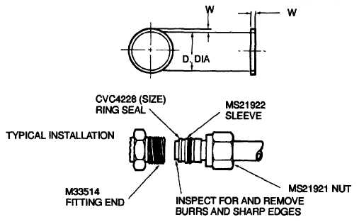
Figure 7-4. Repair (Flareless) Seat
7-15. BLEED AIR PIPELINES. Effective repair of hot
bleed air ducts is considered temporary. Limited repair
may be made as outlined below:
a.
Repair Procedures. Repair should be limited to
areas not exceeding two inches in diameter (Figure 7-5).
b.
Insulation. Remove enough insulation blanket
or permanent insulation to gain access to metal
damaged area. Clean duct surface, and smooth out
damaged area.
c.
Installation. Install flexible stainless steel sheet
(0.016 to 0.018 inch thick) or aluminum sheet with 2
wraps, around entire duct circumference. It should
extend about two inches laterally in each direction
beyond the damaged area or puncture.
d.
Hose Clamp. Install enough hose damps (about
five) to secure repair area. Exercise care when
tightening damps. Overtightening may damage or crush
the bleed air duct.
7-18. ALUMINUM TUBING DAMAGE
7-17. GENERAL INFORMATION . Aluminum tubing is
subject to damage by projectiles and fragments.
Replacement
with
original
replacement
parts
is
desirable, but not essential. In BDAR, tubing and hose,
AN and MS fittings, and other similar components can
be substitutes one for the other. Available time, tools,
skills, and materials will determine which repair option to
use. Whenever a line has complex bends, replacement
of the damaged section with MS fittings, OPTION 3, is
probably the quickest fix.
7-18. LIMITATIONS . None
7-19. OPTION 1. In One Repair (damage to straight
section of tubing).
a.
Materials/Tools Required:
2 Repair Fittings-Shape Memory
Metal/Heat Shrink
Splice Tube
Tubing Cutter
Knife or File
Heat Gun
b.
Procedural Steps:
(1)
Cut and remove damaged section of
tubing, Figure 7-6. Tube ends must be square.
(2)
Clean ends of undamaged tubing with
knife or file.
(3)
Measure the distance between the two
undamaged ends and prepare a tube splice replacement
section of this size. Clean ends of splice section as
done in Step 7-19.c.(2).
7-7


