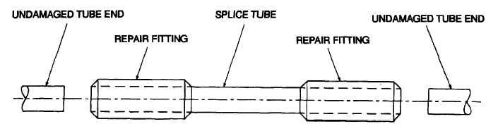
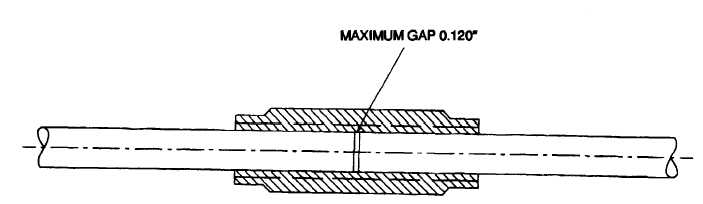
TM 1-1520-240-BD(4)Insert a repair fitting on each end of thesplice tube, and place the splice tube between theundamaged ends of the tube, Figure 7-7.(5)Slide the repair fittings o that they overlapon both the undamaged ends and the splice tube. Theundamaged end and the splice tube should be butted upto each other at the mid potion of the repair fitting (usetest coupling in BDR kit), Figure 7-8.(6)Press the undamaged tube ends firmlyagainst the splice tube and use the heat gun to blow hotair over the repair fitting. This will cause the fitting toshrink down on the tube ends.(7)Record BDAR action taken.Figure 7-7. Splice Repair AssemblyFigure 7-8. Repair Fitting and Tube installation7-9
Integrated Publishing, Inc. - A (SDVOSB) Service Disabled Veteran Owned Small Business