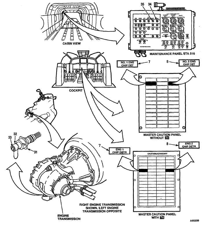
TM 55-1520-240-T6-2.3TRANSMISSION CHIP DETECTORS AND DEBRIS SCREENS OPERATIONAL CHECK (Continued)6-2.3TASKRESULT46.Remove right engine transmission chip detector plug(31)and inspect it. (Refer to TM 55-1520-240-23.)47.Connect connector to plug (31).48.Place a jumper wire between chip detector body (32)NO. 2 ENG CHIP DET (Without 74 ) ENG 2 CHIP DETRand chip detector ring (33).(With 74capsule (8) shall come on. RIGHT TRANS-MISSION CHIP DETECTOR indicator (34) shall changeto black-and-white fan. If capsule (8) is not on or indicator(34) is still black, go to Task 6-2.20.49.Remove jumper wire. Install right engine transmis-NO. 2 ENG CHIP DET (Without 74)ENG 2 CHIP DETRsion chip detector plug (31). (With 74 ) capsule (8) shall go out.50.Remove left engine transmission chip detector plug(31)and inspect it. (Refer to TM 55-1520-240-23.)51.Connect connector to plug (31).52.Place a jumper wire between chip detector body (32)NO. 1 ENG CHIP DET (Without 74 )ENG 1 CHIP DETRand chip detector ring (33).(With 74 ) capsule (7) shall come on. LEFT TRANSMIS-SION CHIP DETECTOR indicator (35) shall change toblack-and-white fan. If capsule (7) is not on or indicator(35) is still black, go to Task 6-2.21.53.Remove jumper wire. Install left engine transmissionNO. 1 ENG CHIP DET (Without 74 ) ENG 1 CHIP DETRchip detector plug (31).(With 74 capsule (7) shall go out.54.Set GND switch (6) to RESET, then to GND.Indicators (29, 30, 34, and 35) shall change to all-black.GO TO NEXT PAGEChange 17 6-39
Integrated Publishing, Inc. - A (SDVOSB) Service Disabled Veteran Owned Small Business