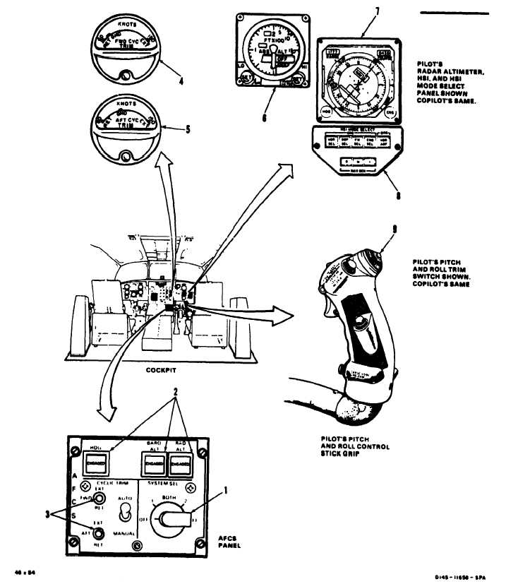
TM 55-1520-240-T11-3.2 AFCS VISUAL CHECK11-3.2INITIAL SETUPApplicable Configurations:AllTools:Aircraft Mechanic’s Tool Kit,NSN 5180-00-323-4692Materials:NonePersonnel Required:35K10 Avionic MechanicReferences:TM 55-1520-240-23Equipment Condtion:TM 55-1520-240-23Battery DisconnectedElectrical Power OffHydraulic Power OffPylon Left WorkPlatform OpenForward Left WorkPlatform OpenFlight Controls Closet AcousticBlanket RemovedElectronic Compartment AcousticBlanket RemovedFlight Controls Closet PanelOpenTASKRESULT1.2.3.4.5.6.7.8.Check AFCS panel.Check FWD and AFT CYC TRIM indica-tors (4 and 5).Check pilot’s radar altimeter (6).Check pilot’s HSI (7).Check pilot’s HSI MODE SELECT panel(8).Check pilot’s pitch and roll trim switch(9).Repeat steps 4, 5, and 6 for copilot’s radaraltimeter HSI, and HSI MODE SELECT panel(6, 7, and 8). then go to step 8.Check copilot’s pitch and roll trimswitch (9).If knob (1) is loose, tighten it. If any switch (2 or 3)is damaged, replace AFCS panel.If either indicator (4 or 5) is damaged, replace it.If altimeter (6) is damaged, replace it.IF HSI (7) is damaged, replace it.If panel (8) is damaged, replace it.If switch (9) is damaged. replace it.If switch (9) is damaged, replace it.GO TO NEXT PAGE11-44
Integrated Publishing, Inc. - A (SDVOSB) Service Disabled Veteran Owned Small Business