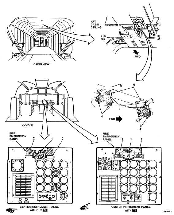
TM 55-1520-240-T12-3.3 FIRE EXTINGUISHING SYSTEM VISUAL CHECK12-3.3INITIAL SETUPReferences:TM 55-1520-240-23Applicable Configurations:AllEquipment Condition:TM 55-1520-240-23:Tools:Battery DisconnectedAircraft Mechanic's Tool Kit,Electrical Power OffNSN 5180-00-323-4692Hydraulic Power OffMaterials:NonePersonnel Required:Medium Helicopter RepairerTASKRESULT1.Check FIRE EXT AGENT switch (1). If switch (1) is loose or damaged, tighten or replace it asrequired.2.Check NO. 1 ENGINE and NO. 2 ENGINE fire handlesIf either fire handle (2) is loose or damaged, tighten or(2).replace it as required.3.Check fire extinguisher (3).If either fire extinguisher (3) is loose, tighten it. If wiring tocartridges (4) is damaged, repair or replace it as required.4.Read gage (5) on each fire extinguisher (3). If either gage (5) pressure reading is below followinglimits, replace fire bottle.TemperaturePressure-40°C (-40F)292 - 370 psi-29°C (-40°F)320 - 400 psi-18°C (0°F)355- 437 psi-7°C (19°F)396 - 486 psi4°C (39F)449 - 540 psi15°C (59°F)518- 618 psi27°C (81 °F)593 - 702 psi30°C (100F)691 - 784 psi52°C (126°F)785- 902 psiFOLLOW-ON MAINTENANCE:NoneEND OF TASK12-56 Change 23
Integrated Publishing, Inc. - A (SDVOSB) Service Disabled Veteran Owned Small Business