TM 55-1520-240-T
4-11.3 GAS PRODUCER CONTROL SYSTEM (N1) OPERATIONAL CHECK
4-11.3
INITIAL SETUP
References:
Applicable Configurations:
TM 55-1520-240-23
With 74
Equipment Condition:
Tools:
TM 55-1520-240-23:
Electrical Repairer's Tool Kit,
Battery Connected
NSN 5180-00-323-4915
Electrical Power On
Materials:
Hydraulic Power Off
None
Visual Check of Gas Producer Control System
Performed (Task 4-11.2)
Personnel Required:
Aircraft Electrician
TASK
RESULT
1.
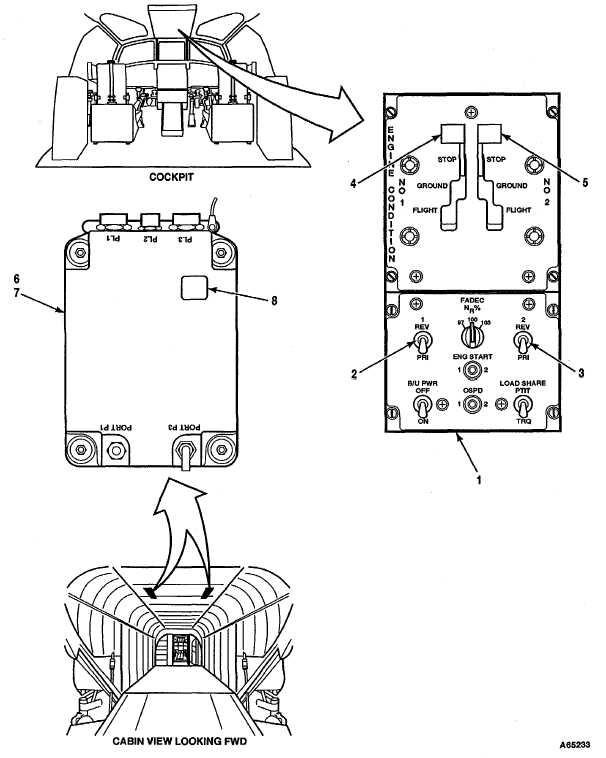
On FADEC panel (1), check NO. 1 and NO. 2 REV/PRI
If switches are not at PRI, set switches to PRI.
switches (2 and 3) are at PRI.
2.
Move ENGINE CONDITION NO. 1 and NO. 2 levers (4
If display shows 88, go to step 3.
and 5) to GROUND. Look at DECU No. 1 and No. 2 (6
If display shows A5 and/or B6, go to task 4-11.4.
and 7) fault display (8).
If display is blank or shows a code other than 88, go to
task 4-12.4.
3.
Move ENGINE CONDITION levers (4 and 5) to STOP.
If display shows A5 and/or B6, go to task 4-11.4.
Look at DECU No. 1 and No. 2 (6 and 7) fault display (8).
If display is blank or shows a code other than 88, go to
Task 4-12.4.
FOLLOW-ON MAINTENANCE:
TM 55-1520-240-23:
Hydraulic power off.
Electrical power off.
Battery disconnected.
END OF TASK
Change 17 4-251


