TM 55-1520-240-T
4-12.3 FULL AUTHORITY DIGITAL ELECTRONIC CONTROL (FADEC) VISUAL CHECK
4-12.3
FAULT ISOLATION PROCEDURE
References:
INITIAL SETUP
TM 1-2840-265-23
TM 55-1520-240-23
Applicable Configurations:
With 74
Equipment Condition:
TM 55-1520-240-23:
Tools:
Battery Disconnected
Electrical Repairer's Tool Kit,
Electrical Power Off
NSN 5180-00-323-4915
Hydraulic Power Off
Materials:
Controls Closet Acoustic Blanket Removed
None
Controls Closet Panel Open
Personnel Required:
Engine Work Platforms Open
Aircraft Electrician
Engine Access Covers Open
TASK
RESULT
1.
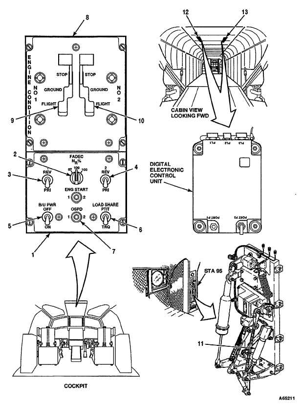
Check FADEC control panel (1).
If NR% control knob (2) is loose or damaged, tighten or
replace it as required. If either engine PRI/REV switch (3
or 4) is loose or damaged, tighten or replace it as
required. If B/U PWR OFF/ON switch (5) is loose or
damaged, tighten or replace it as required. If LOAD
SHARE PTIT/TRQ switch (6) is loose or damaged, tighten
or replace it as required. If OSPD 1/2 switch (7) is loose
or damaged, tighten or replace it as required.
2.
Check ENGINE CONDITION control quadrant (8).
If either NO. 1 or NO. 2 lever (9 or 10) is loose or
damaged, replace the quadrant.
3.
Check thrust control position transducer (11).
If thrust control position transducer (11) is loose or
damaged, tighten or replace it as required. If wiring or
connector to transducer is damaged, repair or replace
wiring or connector as required.
4.
Check DECU (Digital Electronic Control Unit) NO.1 (12).
If DECU NO. 1 (12) is loose or damaged, tighten or
replace it as required. If wiring to DECU NO. 1 is
damaged, repair or replace it as required.
5.
Check DECU (Digital Electronic Control Unit) NO. 2 (13).
If DECU NO. 2 (13) is loose or damaged, tighten or
replace it as required. If wiring to DECU NO. 2 is
damaged, repair or replace it as required.
GO TO NEXT PAGE
4-264 Change 17


