TM 55-1520-240-T
5-1.2 CENTRIFUGAL DROOP STOP OPERATIONAL CHECK
5-1.2
INITIAL SETUP
Equipment Condition:
TM 55-1520-240-23:
Applicable Configurations:
Battery Connected
All
Electrical Power On
Hydraulic Power On
Tools:
Centrifugal Droop Stop Visual Check Com-
None
pleted (Task 5-1.1)
Materials:
None
General Safety Instructions:
Personnel Required:
100C0 Army Rotary Wing Aviator (2)
When rotors are turning, use care
67U20 Medium Helicopter Repairer
outside helicopter. Stay outside
rotor disk area in front of heli-
References:
copter. Do not climb on top of
TM 55-1520-240-23
helicopter until blades stop.
TM 55-1520-240-10
Serious injury or loss of life can
occur if personnel are struck by a
moving blade.
1. Have pilot start engines and stabilize rotors at
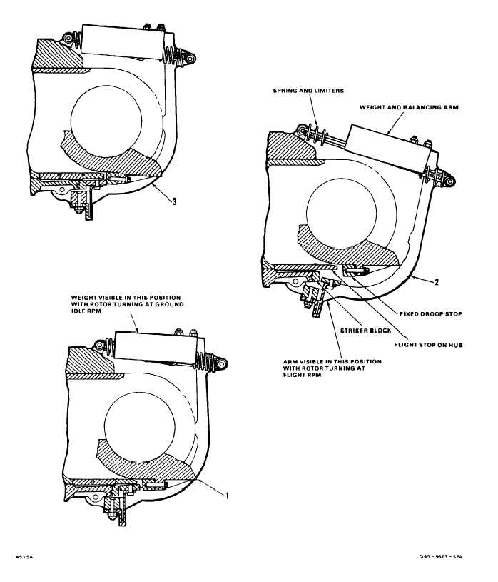
Observe that weights remain in cut-in position (1).
ground idle rpm.
NOTE
Balancing weights are visible during
rotation. Weights can be seen at cut-
in position (1) (stop engaged) or at
cut-out position (2) (stop disen-
gaged)
2. Have pilot operate engines at flight rpm.
3. Have pilot shut down both engines.
A balancing arm and weight that
does not return to cut-in position
(stop engaged) will cause a
hazardous blade condition during
shutdown in gusty weather.
Observe that weights have moved to cutout posi-
tion (2) as rotor speed increases to flight rpm.
As blades slow down, note rotor rpm at which
balancing arms and weights return to cut-in posi-
tion. Balancing arm and weights shall reach cut-in
position at about ground idle rpm. If not refer to
TM 55-1520-240-23.
FOLLOW-ON MAINTENANCE:
TM 55-1520-240-23:
Battery Disconnected
Electrical Power Off
Hydraulic Power Off
No. 1 and No. 2 Engines Shut Down
Droop Stop Shrouds Installed
END OF TASK
5-4