TM 55-1520-240-T
5-2.3 ROTOR BLADE TRACKING AND BALANCING SYSTEM OPERATIONAL CHECK
5-2.3
INITIAL SETUP
Equipment Condition:
Applicable Configurations:
TM 55-1520-240-23:
Tracking with Strobex
Battery Connected
Tools:
None
Materials:
None
Personnel Required:
Rotary Wing Aviator (2)
Aircraft Electrician
References:
TM 55-1520-240-23
Electrical Power On
Hydraulic Power On
Rotor Blade Tracking and Balancing System Visual
Check Performed (Task 5-2.2).
Helicopter Prepared for In-Flight Blade Balancing
Tracking Targets Installed
TASK
RESULT
1.
2.
3.
4.
5.
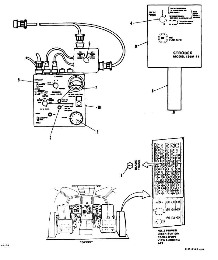
Check that BLADE TRACK circuit breaker (1) is
closed.
Have pilot start engines and stabilize rotors at 100
percent rpm. Prepare strobex (9) for Ground Track,
reference TM 55-1520-240-23. Set function switch
(5) to A. Press VERIFY TUNE switch (2).
Press trigger (8).
If Blade Track circuit breaker (1) is open, close it. If
it opens again, go to task 5-2.4.
Lights on clock angle indicator (3) shall come on at
12, 4, and 8 o’clock positions. If not, go to task
5-2.5.
Strobex flash tube shall flash. Aim at targets. (1
o’clock, Fwd Rotors, 11 o’clock, Aft Rotors.) Targets
shall be visible. If not, go to task 5-2.6.
IPS meter (7) shall move up scale at both positions
and not return to zero. If the IPS meter does not
move or moves and then returns to zero, go to task
5-2.7.
IPS meter (7) shall move up scale at both positions
and not return to zero. If the IPS meter does not
move or moves and then returns to zero, go to task
5-2.8.
Prepare balancer (10) for in-flight balance, reference
TM 55-1520-240-23. Set switch (6) to FWD LAT-
ERAL then AFT LATERAL.
Set switch (6) to FWD VERTICAL, then AFT VER-
TICAL.
FOLLOW-ON MAINTENANCE:
TM 55-1520-240-23:
Battery Disconnected
Electrical Power Off
Hydraulic Power Off
Disconnect Vibrex Equipment
END OF TASK
5-8
Change 10