T M 5 5 - 1 5 2 0 - 2 4 0 - T
7 - 1 . 3 F L I G H T C O N T R O L H Y D R A U L I C S Y S T E M V I S U A L C H E C K ( C o n t i n u e d )
TASK
RESULT
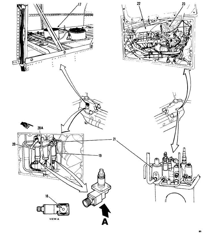
12. Check No. 2 flight control cooling fan
(17).
13. Check filter change indicating button
(18) on two filters (19 and 20).
13.1 Check reading on accumulator gags
(20A).
14. Check both sides of No. 2 power control
module (21).
15. Check No. 2 flight control reservoir
cooler (22).
16. Check duct (23).
If fan (17) is loose or damaged, tighten or replace
it as required. If fan screen is clogged, clean it. If
connector to fan is loose or damaged, tighten or
replace it. If wiring to connector is damaged,
repair or replace it.
If either button (18) is extended, go to task 7-1.6.
Gage (20A) should be within limits shown on
service chart in TM 55-1520-240-23. If it is not,
service accumulator. Refer to TM 55-1520-240-
23. If reading still not correct, replace accumula-
tor.
If module (21) is loose or damaged, tighten or re-
place it as required. If any tube to module is loose
or damaged, tighten or replace it. If any connector
on module is loose or damaged, tighten or replace
it. If wiring to any connector is damaged, repair or
replace it.
If cooler (22) is loose or damaged, tighten or re-
place it as required. If any tube to cooler is loose
or damaged, tighten or replace it as required. If
any connector on cooler is loose or damaged,
tighten or replace it as required. If wiring to any
connector is damaged, repair or replace it as re-
quired.
If duct (23) is loose or torn, tighten or replace it as
required.
7 - 1 . 3
GO TO NEXT PAGE
7-10
Change 1