TM 55-1520-240-T
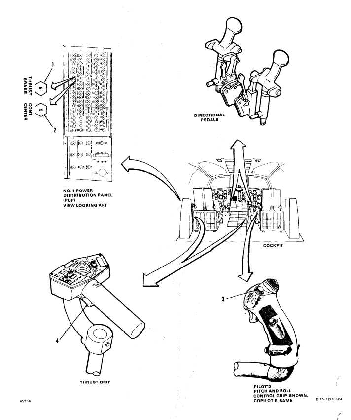
11-2.3 ARTIFICIAL FEEL – MAGNETIC BRAKES OPERATIONAL CHECK
11-2.3
INITIAL SETUP
References:
Applicable Configurations:
TM 55-1520-240-23
All
Equipment Condition:
Tools:
TM 55-1520-240-23:
None
Battery Connected
Materials:
Electrical Power On
None
Hydraulic Power On
Personnel Required:
Artificial Feel - Magnetic Brakes Visual Check
Medium Helicopter Repairer
Performed
TASK
RESULT
1.
Check that THRUST BRAKE circuit breaker (1)
is closed.
2.
Check that CONT CENTER circuit breaker (2) is
closed.
CHECK ARTIFICIAL FEEL AND PILOT CONTROL
OF MAGNETIC BRAKES
CHECK CIRCUIT BREAKERS
If circuit breaker (1) is open, close it. If it opens
again, go to task 11-2.4
If circuit breaker (2) is open, close it. If it opens
again, go to task 11-2.5.
3.
4.
5.
Press and hold pilot CENTERING DEVICE RE-
LEASE switch (3). Center pilot pitch and roll
control stick and directional pedals. Release
CENTERING DEVICE RELEASE switch.
Press and hold pilot CENTERING DEVICE RE-
LEASE switch (3). Move pilot control stick
through longitudinal travel range. Position
control 1 inch forward of center position. Re-
lease switch.
Move pilot control stick 1 inch forward and
release control stick. Move pilot control stick
1 inch aft and release control stick.
Control stick and directional pedals shall center eas-
ily and remain there after CENTERING DEVICE RE-
LEASE switch (3) is released. If both control stick
and directional pedals do NOT remain centered, go
to task 11-2.6. If either control stick or directional
pedals do not remain centered, continue opera-
tional check to identify problem.
Control stick shall move easily through longitudinal
travel range and remain at selected position when
switch (3) is released. If it does not, go to task 11-
2.7.
Control stick shall return to original position when
control stick is released. If it does not, go to task
11-2.7
11-14
Change 12
GO TO NEXT PAGE