TM 55-1680-358-12&P
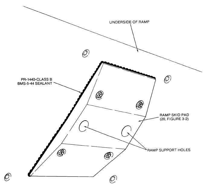
Figure 2-19. Ramp Skid Pad Installation
d. Left- and Right-Hand Inboard Ramp Roller
Assemblies. Install left- and right-hand inboard ramp
roller assemblies (13 and 14) as follows:
(1) Position left and right-hand inboard ramp
roller assemblies as shown in Figure 2-18 over the
locations from which bolts were removed (para 2-9a.(4)
and 2-9a.(5)).
(2) Install one countersunk bolt (27, Figure 3-2)
at or near B.L. 10.000 through ramp center roller
mounting plate (10, Figure 3-11) at transition roller
assembly, station 486.625 (19 and 45, Figure 3-10), for
each inboard ramp roller assembly (13 and 14, Figure 3-
2).
(3) Install two hex head bolts (35) and flat
washers (42) at B.L. 7.186 and B.L. 6.057 through
ramp center roller mounting plate (10, Figure 3-11) at
each inboard ramp roller assembly (13 and 14, Figure 3-
2).
(4) Install two hex head bolts (32) and flat
washers (42) through the remaining holes in each ramp
center roller mounting plate (10, Figure 3-11).
2-29

