TM 1-1520-240-10
3-3-5
NOTE
If synchronizing becomes necessary in flight
with the AFCS on, position the SWIVEL
switch to UNLOCK. After synchronization is
complete, position the SWIVEL switch to
LOCK. This prevents unwanted yaw axis in-
puts.
c. Manual Synchronization. If power has been ap-
plied to the system with the compass slaving switch at
FREE or if the system has been operated in the free
directional gyro mode for a period of time, the compass
cards will not be aligned with the magnetic heading of the
helicopter. The system can be reset to the correct mag-
netic heading by pushing and turning the PUSH TO SET
knob in the direction of the symbol indicated by the an-
nunciator pointer until the pointer is centered. If the slav-
ing switch is then set to SLAVED, the compass cards will
maintain correct magnetic heading.
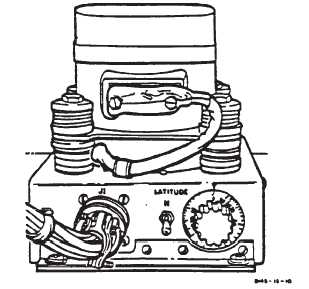
Figure 3-3-4. Directional Gyro (CN-998/ASN-43)
3-3-11. Doppler Navigation Set (AN/ASN-128).
NOTE
When the Airborne Navigation Set AN/
ASN-149 (Global Positioning System GPS) is
installed, the Doppler Navigation Set AN/
ASN-128 is controlled by the GPS CDU. For
a description of the Airborne navigation Set
and Doppler Navigation Set.
a. The doppler navigation set (fig. 3-3-5) is a self-
contained navigation system that does not require any
ground-based aids. The system provides worldwide nav-
igation with position readout available in both universal
transverse mercator (grid) (UTM) and latitude and longi-
tude (lat/long). Navigation and steering is done using
lat/long coordinates, and bilateral UTM-lat/long conver-
sion routine is provided for UTM operation.
b. The system in conjunction with heading data from
the gyro compass, and pitch and roll data from the copi-
lot’s attitude gyro, provides velocity, position, and steer-
ing information from ground level to 10,000 feet.
c. The computer-display unit (CDU) is on the canted
console, between the pilot and copilot positions. Course
deviation, bearing, distance to destination, and NAV GO/
NOGO are also presented to the HSI. Built in test equip-
ment (BITE) continuously monitors system operation. If
a failure occurs, a malfunction indicator lamp will light
and coded data, indicating the failed component, will be
displayed on the CDU when the MODE switch is set to
TEST. Power to operate the set is supplied by the No. 2
DC bus through the NAV DOPPLER circuit breaker on
the No. 2 PDP, and the No. 1 AC instrument bus through
the NAV DOPPLER circuit breaker on the No. 1 PDP.