TM 1-1520-240-10
4-3-9
CAUTION
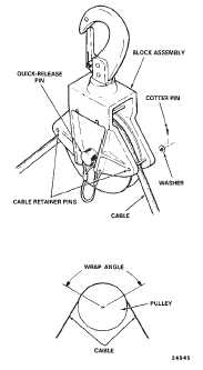
Some pulley block assemblies have
flanges with cable retainer pins as shown
in fig. 4-3-9 (Sheet 1 of 2). These pins
should be installed only if the cable makes
a wrap angle of 180_ or more around the
pulley. Otherwise, the cable will bind on
the pins and overload the winch and cable.
When not in use, the pins and attaching
hardware should be stowed in the contain-
er provided for the hoist accessories.
(2)
Install the pulley block assembly on the floor
at sta 140, the overhead on the aft face of sta 120 bulk-
head and the cable cutter pulley block over the rescue
hatch (fig. 4-3-9 (Sheet 2 of 2)).
(3)
Reeve the cable through the pulley at each
location by first removing the quick-release pin, removing
the pulley and positioning the cable over the pulley. Rein-
stall each pulley and secure with the quick-release pin
(fig. 4-3-9 (Sheet 1 of 2)).
Figure 4-3-9. Hoisting System (Sheet 1 of 2)
WARNING
The quick-disconnect cover guard must
be installed during rescue and cargo op-
erations. Otherwise, the hook assembly
can be inadvertently disconnected from
the winch cable which can result in loss of
life or the load or serious injury to operat-
ing personnel. For personnel rescue, the
cable must touch the ground or water
prior to touching personnel or a danger-
ous static electrical shock may result.
(4)
Attach the winch cable to the cable hook
assembly by depressing the lock rings on each end of the
quick-disconnect device, inserting the ball ends of the
winch and hook assembly cables into the quick-discon-
nect device and releasing the lock rings. Install the quick-
disconnect cover guard.
WARNING
Slack must be removed from the cable
train before applying the full load to the
winch system to prevent shock and over-
load of the system and possible injury to
the personnel being hoisted.
CAUTION
Ensure that the load is clear of the ground
and all obstacles before proceeding from
hover to forward flight. Do not exceed 600
pounds. An overload can result in damage
or failure of the support structure for the
overhead cable pulley.
(5)
Reel the cable out and attach the cable hook
to load — Reel in or out as required.
g.
When electrical power to the winch is not avail-
able, the winch may be operated in emergency mode as
follows:
CAUTION
When the winch is operated in emergency
mode, the cable limit switches are dis-
abled. To avoid kinking the cable, stop the
winch when there is no less than 3 turns of
cable on the drum. Stop reeling the cable
in when the quick-disconnect guard as-
sembly contacts the pulley and fairlead
(fig. 4-3-1).
(1)
Remove electrical connectors from the hoist
control valve and hoist control shutoff valve on the left
bulkhead of the heater compartment (fig. 4-3-10).


