TM 1-1520-240-10
2-3-4
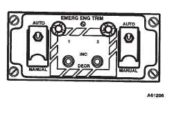
Figure 2-3-2. Emergency Engine Trim Panel 712
2-3-11. Emergency Power System. 712
CAUTION
To prevent damage, monitor the torque
and the PTIT indicators when operating
with emergency power. Failure to observe
these indicators could result in serious
damage to the drive train and engine.
An emergency power system is included with T55-L-712
engines. With the emergency power system, increased
power is available on pilot demand and is actuated by
raising the thrust control into the emergency power
range. Refer to Chapter 5 for limitations on its use.
When fuel flow increases to the point where PTIT is 890_
to 910_C, the EMERG PWR lights will illuminate on the
copilot and pilot instrument console (17, fig. 2-1-7 and 18,
fig. 2-1-9). If temperature is maintained in this range for
more than 5 seconds, the associated indicator will apply
28-volt DC from the ENGINE NO. 1 and / or NO. 2 START
& TEMP circuit breaker to the EMERGENCY POWER
panel. With 28-volt DC applied to the panel, the applica-
ble emergency power timer will start, and the indicator
will display a black-and-white flag. When thrust is re-
duced below the emergency power level, the emergency
power light will extinguish and the timer will stop. Howev-
er, the emergency power indicator will continue to display
the black-and white flag. The flag can be reset on the
ground only.
WARNING
Before flight, be sure the two topping
stops are in their stowed position on the
right side of the console. If stops are not
stowed, be sure the stops are not installed
on the fuel controls before you start the
engine. Failure to check may result in in-
ability to achieve emergency power in an
emergency.
Topping stops are stowed on each helicopter. The stops
are installed on the N1 control of each engine for mainte-
nance engine topping checks. The stops provide an es-
tablished fuel flow when topping. When not in use, the
stops are stowed on the right side of the center console
aft of the pedals.
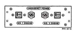
2-3-12. EMERGENCY POWER Panel. 712
The EMERGENCY POWER panel is located on the over-
head switch panel (fig. 2-3-3). It consists of an emergen-
cy power indicator and a digital timer for each engine.
They are labeled NO. 1 and NO. 2 ENGINE. The timer
counts the minutes that emergency power is in use.
2-3-13. Oil Supply System.
The oil supply system is an integral part of the engine.
The oil tank is part of the air inlet housing and the filler
neck is on the top of the housing. An oil level indicator is
on the left side of the engine inlet housing. Refer to table
2-15-1 for the tank capacity. If the oil level decreases to
about 2 quarts usable, the corresponding ENG OIL LOW
caution capsule will illuminate.
Figure 2-3-3. Emergency Power Panel 712
2-3-14. Engine Start System. 712
The engine start system includes the hydraulic starters
on each engine, the engine start valves and the solenoid-
operated pilot valves on the utility system pressure con-
trol modules, the START switch, and the start fuel sole-
noids and ignition exciters on the engines.
When the start switch is moved to MTR, the respective
engine STARTER ON indicator light illuminates and the
start valve opens (fig. 2-3-4). The start valve applies
utility system pressure from the APU to the engine start-
er: rotating the engine starter and compressor. At 15
percent N1, the ENG COND lever is moved to GND. The
start switch is immediately moved to START, energizing
the ignition exciter. Start fuel is sprayed into the combus-
tor and combustion begins. Before PTIT reaches 200_C,
the START switch is manually released to MTR. At MTR,
the start fuel valve is closed and the ignition exciter is
deenergized.
The engine then accelerates to ground idle speed. At 50
percent N1, the START switch is manually moved to the
locked OFF position. At OFF, the pilot valve closes, clos-
ing the start valve and deenergizing the STARTER ON
indicator light. A relay in each engine start circuit is ener-
gized when either START switch is at MTR or START.
The relay, when energized, disables the start circuit of
the opposite engine, thus preventing simultaneous dual
engine starts. Power is supplied by the No. 1 and No. 2
DC essential buses through the ENGINE NO. 1 and NO.
2 START & TEMP AND IGN CIRCUIT BREAKERS ON
THE No. 1 AND No. 2 PDP.


