TM 1-1520-240-10
2-3-5
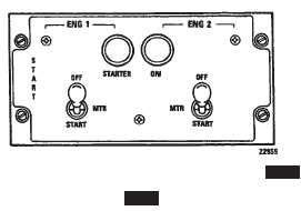
Figure 2-3-4. ENGINE START PANEL 712
2-3-15. START Panel. 712
The START panel is located on the overhead switch pan-
el (fig. 2-3-4). It consists of the ENG 1 and ENG 2 START-
ER ON indicator lights and two start switches.
a.
Start Switches. The switches are labeled OFF,
MTR, and START. They are locked in OFF, detented in
MTR and spring-loaded from START to MTR. At MTR,
the engine is rotated by the starter, but ignition and start
fuel circuits are deenergized. At START, the engine is
rotated with start fuel and the ignition circuits are energi-
zed. MTR is selected during starting, in case of engine
fire or to clear the combustion chamber.
b.
STARTER ON Indicator Lights. The STARTER
ON indicator lights will illuminate when the associated
START switch is moved to MTR or START. The light
alerts the pilots when the START switch is inadvertently
left at MTR. Power is supplied by the No. 1 and No. 2 DC
essential buses through the ENGINE NO. 1 and NO. 2
START & TEMP circuit breakers on the No. 1 and No. 2
PDP.
2-3-16. Ignition Lock Switch.
An ignition system lock switch (11, fig. 2-1-3) is installed
on the right side of the console forward of the thrust lever.
The key-operated switch prevents unauthorized use of
the helicopter. When the switch is off, the circuits of the
ignition exciters and the start fuel solenoids of both en-
gines are open. Therefore, the engines cannot be star-
ted. Be sure both START switches are OFF before turn-
ing the ignition lock switch ON or OFF.
2-3-17. Engine Instruments and Cautions.
The engine instruments are the gas producer tachome-
ter, the dual torquemeter, power turbine inlet tempera-
ture (PTIT), fuel flow, oil pressure and oil temperature
indicators. The caution capsules are the NO. 1 and NO.
2 ENGINE OIL LOW and the NO. 1 and NO. 2 ENG CHIP
DET.
2-3-18. Gas Producer Tachometer.
Two gas producer tachometers (N1), one for each en-
gine, are on the center instrument panel (6, fig. 2-1-8 and
6, 2-1-12), above the PTIT indicators. Each tachometer
displays gas producer turbine speed in percent of N1.
Each tachometer operates from power supplied by a gas
producer tachometer generator on the accessory gear
box section of each engine. 712 The outer scale of the
tachometer is calibrated from 0 to 100 in increments of
two. The smaller, vernier scale is calibrated from 0 to 10,
in increments of one. 714A The tachometer is calibrated
from 0 to 110.
2-3-19. Torquemeter.
One torquemeter is on the copilot instrument panel and
the other on the pilot instrument panel (1, fig. 2-1-7 and
17, fig. 2-1-9). Each torquemeter has two pointers, one
for each engine, labeled 1 and 2. Each torquemeter has
a range of 0 to 150 percent. The system consists of a
power output shaft, torquemeter head assembly, power
supply unit, 714A ratio detector power supply unit
(RDPS), and a torquemeter junction box. Power to oper-
ate the torquemeter is provided by No. 1 and No. 2 AC
buses through the ENGINE NO. 1 and NO. 2 TORQUE
circuit breakers on the No. 1 and No. 2 PDP. Power for
the power supply unit 714A and RDPS is provided by
the No. 1 and No. 2 DC buses through the DC ENGINE
NO. 1 and NO. 2 TORQUE circuit breakers on the No. 1
and No. 2 PDP.
2-3-20. Power Turbine Inlet Temperature Indica-
tors.
Two power turbine inlet temperature (PTIT) indicators,
one for each engine, are on the center instrument panel
(7, fig. 2-1-8, 7, fig. 2-1-12). Each indicator is calibrated
from 0_ to 1,200_C. The temperatures registered on the
PTIT indicator are transmitted by chromel-alumel ther-
mocouples. the thermocouples sense gas temperature
at the power turbine inlet and transmit an average gas
temperature reading to the PTIT indicator in the cockpit.
712 When power turbine inlet temperature increases to
the emergency power range, the EMERG PWR indicator
light will illuminate and DC power is supplied to the
EMERGENCY POWER panel. 714A When power turb-
ine inlet temperature increases to the contingency power
range, the ENG CONT PWR master caution advisory
panel capsule will illuminate.
2-3-21. Engine Oil Pressure Indicator.
An engine oil pressure indicator on the center instrument
panel is provided for each engine (17, fig. 2-1-8 and
2-1-12). Each indicator relates pressure sensed at No. 2
bearing by an oil pressure transmitter mounted near the
engine. Each engine oil pressure indicator displays a
pressure range from 0 to 200 psi. Power to operate the
engine oil pressure circuit is supplied by the AC instru-
ment buses through the ENGINE NO. 1 and NO. 2 OIL
PRESS circuit breakers on the No. 1 and No. 2 PDP.
2-3-22. Engine Oil Temperature Indicator.
Two engine oil temperature indicators are on the center
the instrument panel (18, fig. 2-1-8 and 2-1-12). Each
engine oil temperature indicator is calibrated from -70_
to + 150_C. A temperature probe within the lubrication
lines of the engine, before the fuel-oil cooler, is the point
at which the temperature is sensed. Power to operate the
resistance-type oil temperature circuit is supplied by the
No. 1 and No. 2 DC buses through the ENGINE NO. 1