TM 1-1520-240-10
2-4-1
SECTION IV. FUEL SYSTEM
2-4-1. Fuel Supply System.
The fuel supply system furnishes fuel to the two engines,
the heater, and the APU. Two separate systems, con-
nected by crossfeed and a pressure refueling lines are
installed. Provisions are available within the cargo
compartment for connecting Extended Range Fuel Sys-
tem (ERFS) and ERFS II to the two fuel systems.
Each fuel system consists of three fuel tanks contained
in a pod on each side of the fuselage. The tanks are
identified as forward auxiliary, main, and aft auxiliary
tanks. During normal operation, with all boost pumps
operating, fuel is pumped from the auxiliary tanks into the
main tanks, then from the main tanks to the engine. A
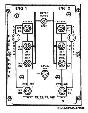
simplified fuel flow diagram is engraved on the FUEL
CONTR (control) panel on the overhead switch panel
(fig. 2-4-1).
When the fuel is consumed in an auxiliary tank, the fuel
pump is automatically shut off and a check valve closes
to prevent fuel from being pumped back into that tank.
Should a fuel pump fail in an auxiliary tank, the fuel in that
tank is not usable. However, should both boost pumps
fail in a main tank, fuel will be drawn from the main tank
as long as the helicopter is below 6,000 feet Pressure
Altitude (PA).
Fuel is delivered to the APU from the left main tank and
to the heater from the right main tank. Fuel system
switches and the auxiliary tank low pressure indicating
lights are on the FUEL CONTR panel, the fuel line pres-
sure caution capsules are on the master caution panel,
and the fuel flow meter is on the center instrument panel.
The single point pressure refueling panel and nozzle
adapter are on the right side above the forward landing
gear. Refer to Section XV for fuel tank capacities, fuel
grades, and fuel system servicing procedures.
2-4-2. Fuel Tanks.
The fuel tanks are crashworthy self-sealing tanks with
breakaway fittings. The main fuel lines are constructed
of self-sealing material. Penetration of the tank wall or a
fuel line by a projectile exposes the sealant to the fuel,
activates the sealant, and close the hole.
Breakaway self-sealing fittings are installed where the
main fuel lines connect to the fuel tank and adjacent
structure. Under high impact loads, the fittings shear or
break at predetermined locations, seal themselves, re-
tain the fuel, keeping fuel loss and post-crash fire hazard
to a minimum. Electrical cables having lanyard-release
type connectors are installed where the cables attach to
adjacent structure. The connectors automatically re-
lease if the fuel tank breaks away from the pod.
Each main tank contains two fuel boost pumps, three fuel
quantity probes, a jet pump for evacuating the pressure
refueling system, a dual pressure refueling shutoff valve,
a dual fuel level control valve, and a gravity filler port.
Each auxiliary tank contains a fuel pump with automatic
shutoff feature, a quantity probe, a dual pressure refuel-
ing shutoff valve, and a fuel level control valve.
Figure 2-4-1. Fuel Control Panel
A rollover vent system is installed in each tank. This
system prevents fuel spillage from the vents should the
helicopter roll over following a crash landing. The vent
system within the tanks have a condensate drain at the
aft end, however, aircraft maneuvering should never
force fuel into the vents. Sump drains are also installed
on the bottom forward end of each tank.
2-4-3. Controls and Indicators.
The fuel controls are the FUEL PUMP switches, XFEED
fuel valve switch, the engine fuel valve, and the manual
defueling valve. Indicators include the crossfeed fuel and
engine fuel valve warning lights, the FUEL QUANTITY
indicator and caution capsules, FUEL flow indicator, AUX
PRESS indicating lights, and FUEL PRESS caution cap-
sules. Refer to para. 2-4-10 for a description of the pres-
sure refueling system controls and indicators.
2-4-4. FUEL CONTR Panel.
The FUEL CONTR panel (fig. 2-4-1) consists of eight
two-position fuel boost pump switches, two PRESS-TO-
TEST AUX PRESS indicating lights, a two-position
XFEED switch, and a two-position REFUEL STA switch.
a.
FUEL PUMP Switches. Each switch controls a
single-speed electrically driven fuel boost pump. La-
beled next to each switch is the name of the pump which
it operates. Each switch has an ON and OFF position.
When one of these switches is at ON, power from the No.
1 or No. 2 DC bus closes the respective pump relay
connecting power from the No. 1 or No. 2 AC bus to