TM 1-1520-240-10
2-3-17
EAPS control switch located in the EAPS control panel
is in the OPEN position and the doors are fully open, and
will extinguish when the switch is in the CLOSE position
and the doors are fully closed.
2-3-44. Differential Pressure Switch.
Each separator is equipped with a differential pressure
switch to determine the air passages of the EAPS unit are
blocked. The switch senses the pressure difference be-
tween the inside and outside of the curved panels of the
EAPS unit. When a differential pressure is detected, the
EAPS 1 FAIL or EAPS 2 FAIL caution lights illuminated.
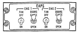
2-3-45. EAPS Switches.
There are four, 2 position toggle switches located on the
EAPS control panel (fig. 2-3-8) situated on the overhead
switch panel.
a.
The ENG 1 and ENG 2 FAN ON/OFF switches
operate the control circuit to provide AC power for the
EAPS fans. The switches receive power from the No. 1
and No. 2 28 volt DC buses through circuit breakers
marked EAPS 1 and EAPS 2 FAN CONT.
b.
The ENG 1 and ENG 2 DOORS CLOSE-OPEN
switch electrically positions the by-pass doors, open pr
closed. The switches receive power from the No. 1 and
No. 2 28-volt DC buses through circuit breakers marked
EAPS 1 and EAPS 2 BYPASS DOORS.
Figure 2-3-8. EAPS Control Panel
1.
EAPS fan exhaust
2.
EAPS rails and slides.