TM 1-1520-240-10
2-5-3
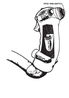
Figure 2-5-2. Cyclic Stick Grip
2-5-5. AFCS Trim Switch.
NOTE
If the longitudinal CCDA fails, it can be recog-
nized by loss of pitch trim or failure of the
centering devise to release. A centering
spring in the pitch axis allows these forces to
be over-come.
The AFCS trim switch (fig. 2-5-2) is used to make small
changes in the pitch (airspeed) and roll attitude while the
AFCS is operating. The switch is spring-loaded to center
off position. Moving the switch forward or aft from center
off position commands an increase (forward) or de-
crease (aft) in airspeed by driving a trim motor in the
longitudinal CCDA.
Moving the switch left or right commands the roll ILCA to
bank the helicopter in the selected direction without mov-
ing the stick. Power is supplied to drive the pitch trim
motor from No. 1 AC bus through CLTV DRIVER ACTR
circuit breaker on the No. 1 PDP.
2-5-6. Directional Pedals.
The directional pedals (7 and 24, fig. 2-1-3) are used for
directional control of the helicopter during flight and while
taxiing with the forward gear off the ground.
When the right pedal is displaced forward, the forward
rotor disk tilts to the right and the aft rotor disk tilts to the
left. The opposite action occurs when the left pedal is
displaced forward. An ILCA is installed to assist the pilot
in moving the pedals.
The pedals are adjusted individually fore and aft by
pressing a lever mounted on the pedal support and mov-
ing the pedal to a new position before repositioning the
lever. Insure that both pedals are adjusted equally (left
and right pedals in same respective hole position) and
pedal adjustment lockpins are engaged. A balance
spring is installed to reduce control sensitivity.
2-5-7. Advanced Flight Control System. (AFCS)
a.
The Advanced Flight Control System (AFCS) sta-
bilizes the helicopter about all axes and enhances control
response. It automatically maintains desired airspeed,
altitude, bank angle, and heading. An automatic turn fea-
ture, coupled to the pilot or copilot HSI (horizontal situa-
tion indicator) is also included in the AFCS.
b.
Built In Test Equipment (BITE) is installed in each
AFCS computer. This equipment is intended for ground
troubleshooting purposes only. An interlock circuit
through the engine condition control box prevents BITE
use anytime either ECL is out of STOP.
c.
Power is supplied to the HDG ENGAGED, BARO
ALT and RAD ALT ENGAGED lights from the DC essen-
tial bus through the CAUTION PNL circuit breaker on the
No. 1 PDP. The No. 1 AFCS receives AC and DC buses
respectively through the AFCS NO. 1 circuit breakers on
the No. 1 PDP. The No. 2 AFCS receives AC and DC
power from the No. 2 AC and DC buses respectively
through the AFCS NO. 2 circuit breakers on the No. 2
PDP.
d.
The AFCS consists of the following compo-
nents:
(1)
A cockpit control panel.
(2)
Two AFCS computers in the avionics
compartment.
(3)
Three ILCA’s in the flight control closet.
(4)
A differential airspeed hold (DASH) actuator
in the flight control closet.
(5)
Two longitudinal cyclic trim (LCT) actuators
are installed, one in the forward upper controls, the other
in the aft upper controls.
(6)
Roll and yaw magnetic brakes, a longitudi-
nal CCDA, and a thrust CCDA are all located in the flight
controls closet.