TM 1-1520-240-10
2-5-5
(1)
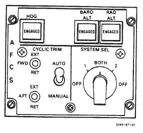
HDG Switch. The HDG (heading) switch is
used in conjunction with the CMD SEL switch either HSI
MODE SELECT panel and the heading bug on either HSI
to select coupled turns. The switch can be used only
when airspeed is above 40 knots. When the switch is
pressed and either CMD SEL switch is pressed, the heli-
copter will automatically turn to and capture the heading
bug on the selected HSI. In addition, the ENGAGED
legend will illuminate. The switch is disengaged by press-
ing it again.
Heading intercept will be at standard rate of 3_ per sec-
ond up to a bank angle limit of 20_ at 133 knots. The
helicopter must be trimmed before engaging the mode
and cyclic stick control inputs should be avoided except
for longitudinal AFCS trim inputs to adjust airspeed.
Figure 2-5-3. Advanced Flight Control System
Panel
Heading select is disengaged if either CENTERING DE-
VICE RELEASE switch is pressed.
(2)
BARO ALT and RAD ALT Switches. The
BARO ALT and RAD ALT are used to select altitude hold
mode. An interlock prevents both switches from being
engaged at the same time. When pressed, the EN-
GAGED legend will illuminate. RAD ALT hold is used
below 1,500 feet AGL. BARO ALT hold is used in forward
flight to maintain a constant cruise altitude or may be
used in HOGE.
b.
SYSTEM SEL Switch. The SYSTEM SEL switch
is a five position rotary switch labeled OFF, 1 BOTH, 2
OFF. Normally, the switch is at BOTH. In this position,
both AFCS are operating at one-half gain. If one system
should fail, the good system is selected and that system
operates at 3/4 gain. At OFF, both systems are inopera-
tive except for CYCLIC TRIM.
c.
CYCLIC TRIM Switches. The AUTO and MANU-
AL switch selects the mode of cyclic trim operation. The
FWD and AFT switches are used to extend or retract the
appropriate cyclic trim actuator.
(1)
AUTO and MANUAL switch. A two-position
switch which is normally placed in AUTO.
(a)
AUTO Mode. In this mode, No. 1 AFCS
controls the forward actuator and the No. 2 AFCS con-
trols the aft actuator.
(b)
MANUAL Mode. In this mode, the ac-
tuator can be controlled with separate FWD and AFT
actuator control switches, using the airspeed indicator
and CYCLIC TRIM indicators.
(2)
FWD and AFT switched. Three- position
switched that can be placed in the EXT (extend) or RET
(retract) position. These switches are spring-loaded to
the center off position. If the cyclic trim actuators fail to
extend or retract as indicated on the CYCLIC TRIM indi-
cators, MANUAL mode can be selected.
2-5-16. Cyclic Trim Indicators.
WARNING
If the longitudinal cyclic trim actuators fail
at the full retract position or are manually
selected to the full retract position, do not
exceed the airspeed limitations shown in
fig. 5-7-1.
The FWD and AFT CYC (cyclic) TRIM indicators (fig.
2-5-4) are on the center instrument panel. The indicators
are labeled 60 RET, GND, 150 EXT. The indicators dis-
play position of the forward and aft LCT actuators relative
to airspeed. During ground operations, the pointer will be
at GND to indicate activation of the landing gear proximi-
ty switches.
2-5-17. AFCS OFF Caution.
Two AFCS OFF caution capsules are on the master cau-
tion/advisory panel ( 712 ,fig. 2-14-5,
714A , fig.
2-14-6). They are labeled 712 NO. 1 AFCS OFF and
NO. 2 AFCS OFF, 714A AFCS 1 and AFCS 2. These
cautions will illuminate when the associated AFCS is
manually shutoff or has failed or the associated DASH is
in a low rate condition. Refer to Chapter 8 AFCS Off Flight
Characteristics.