TM 1-1520-240-10
2-6-1
SECTION VI. HYDRAULIC SYSTEMS
2-6-1. Hydraulic Power Supply System.
The hydraulic power supply system consists of three
separate systems. They are the No. 1 flight control sy-
stem, No. 2 flight control system, and a utility system.
Each system includes a variable delivery pump and res-
ervoir cooler. In addition, each flight control system has
a power control module, and the utility system has a
pressure control module. Each flight control system is
connected to the utility system by a Power Transfer Unit
(PTU). All systems are serviced by a common fill module
and are pressurized to prevent pump cavitation.
2-6-2. Flight Control Systems.
The No. 1 and No. 2 flight control systems are identical.
they ar parallel in operation, hydraulically separated, and
electrically integrated. The flight control system operate
at approximately 3,000 psi, which is reduced to 1,500 psi
for ILCA operation. They power four upper dual boost
actuators (3,000 psi) and four ILCAs (1,500 psi). Each
flight control system powers one piston of each actuator.
No. 1 flight control system is pressurized by a pump on
the forward transmission. No. 2 system is pressurized by
a pump on the aft transmission. The power control mod-
ules consist of pressure-line and return-line filters. No.1
system power control module is in the forward pylon. No.
2 system power control module is in the aft pylon. The
accumulators dampen low frequency pressure surges
and provide stored hydraulic power for peak loads.
The PTU in each system allows ground checkout of the
flight control systems with the rotors stopped. Each PTU
consists of a pump driven by a hydraulic motor which is
pressurized by the utility hydraulic system. The PTU’s
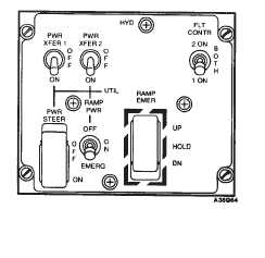
are controlled by the PWR XFER 1 and 2 switches on the
HYD panel in the overhead switch panel.
2-6-3. FLT CONTR Switch.
The FLT CONTR (flight control) switch is located on the
HYD panel in the overhead switch panel (fig. 2-6-1). It is
a three-position center locked switch labeled 2 ON,
BOTH, and 1 ON. this switch can be used to turn off one
of the flight control systems, provided the other one is
operating. Turning off one of the flight control hydraulic
systems disables the corresponding AFCS and causes
the remaining AFCS to make full corrections. In addition,
the respective AFCS OFF and HYD FLT CONTR caution
capsules will illuminate. The FLT CONTR switch shall be
set to BOTH during all flight conditions.
At BOTH , both solenoid valves are deenergized open
and both flight control systems are pressurized. When
the FLT CONTR switch is set to 1 ON, the two-way sole-
noid valve on No. 2 power control module is energized
closed. This causes No. 2 pressure-operated valve to
close, depressurizing No. 2 system. When the FLT
CONTR switch is moved to 2 ON, the two-way solenoid
valve on No. 2 power control module is deenergized
open, and No. 2 system is pressurized. Simultaneously,
No. 1 solenoid valve closes and No. 1 system is turned
off.
2-6-4. Utility Hydraulic System.
The utility hydraulic system supplies hydraulic power to
the wheel brakes, power steering actuator, swivel locks,
centering cams, ramp actuating cylinders, hydraulic car-
go door motor, actuator for the center cargo hook, cargo/
rescue winch control valve, two engine starters. PTU;s
and APU start circuit. When the APU is running, the utility
hydraulic system is pressurized by an APU driven pump.
When the APU is not running and the rotors are turning,
the utility hydraulic system is pressurized by an aft trans-
mission driven pump.
The utility hydraulic system incorporates a pressure con-
trol module which isolates utility subsystems from each
other. When a failure occurs in one utility hydraulic sub-
system, the remaining subsystems continue to operate
normally if the BRK STEER and RAMP PWR switches in
the cockpit are set to OFF.
The APU starting subsystem of the utility hydraulic sys-
tem includes three accumulators which accelerate the
APU to start, maintain reservoir pressure throughout the
start cycle, and control operation of the APU motor pump.
The APU starting subsystem also includes a two-stage
hand pump for charging the APU start accumulators. The
APU is normally recharged by the APU motor-pump after
the APU is started. An additional accumulator in the
brake system provides for limited brake operation in the
event of utility hydraulic system failure. the steering sys-
tem also has an accumulator to keep the swivel locks
engaged when the BRK STEER switch is OFF.
Normal operating pressure range for the utility hydraulic
system is 2500 to 3500 psi. During APU operation pres-
sure is increased to approximately 3350 psi for engine
starting. (See table 2-15-1 for flight control and utility
hydraulic system capacities and fig. 2-15-3 for accumula-
tor precharge pressures.)
Figure 2-6-1. Hydraulics Control Panel


