TM 1-1520-240-BD
b.
Temporary Repair Techniques. Repair
performed under the guidelines of this paragraph may
be used for a period of 140 flight hours. At this time of
the temporary repair is to be inspected and a decision
made to either extend the use of the temporary repair or
make a permanent repair. This paragraph describes
temporary repair techniques for co-axial cable and large
wire-side splices, connection or junction boxes, terminal
board
bridging,
and
insulation
repair
with
heat-
shrinkable tape. Prior to performing any of the listed
repairs, the repair technician must be knowledgeable in
the basic repair procedures and proficient in the use of
the wiring repair tools and materials.
(1)
Co-Axial Cable Splice. The wire repair
kit contains materials for making environmentally
protected splices on aircraft co-axial cables. As these
splices are a new item, and not fully qualified at this
time, splices performed with these materials must be
categorized as temporary, even though performance
loss of a co-axial cable system using these splices in
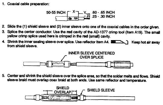
minimal. Figures 9-27 through 9-32 illustrate the basic
procedure to splice co-axial cables of the types noted.
These instructions are the same as the repair material
storage container. One co-axial cable splice is
allowable for every eight feet of co-axial cable length.
Additional splices per cable may be authorized by the
maintenance authority as local conditions warrant.
NOTE
The
item
number
on
each
illustration indicates the location
of the repair material storage
container and/or required tools
within the wiring repair kit portion
of the repair set.
After completing a co-axial splice,
obtain a chart record of the co-
axial cable signature for inclusion
in the aircraft records. This chart
record is to be obtained using the
TDR. Annotate the chart record
with aircraft serial number, date,
cable
number,
vertical
and
horizontal TDR attentions, and
any other data of interest. This
chart record is to be used to verify
the integrity of the repair and
provide a baseline for future
comparison in the event of system
degradation.
Item B24 Coax Splice for RG-136/U and RG179B/U
Figure 9-27. Item B24 Coax Spike
9-24


