TM 1-1520-240-BD
d.
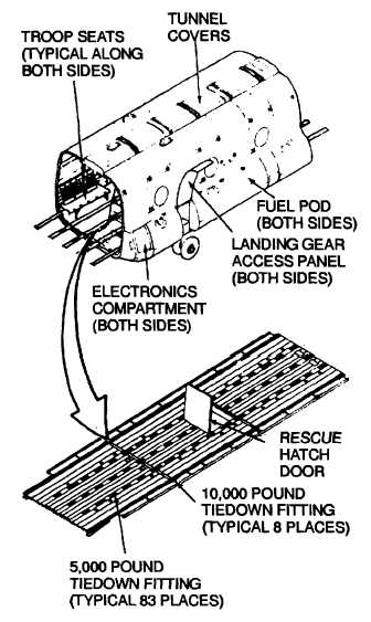
Cabin Fuselage. (Figure 2-31). The cabin
section provides the major carrying capacity of the
helicopter. It can be fitted to carry troops, litters, cargo,
or any combination of the three. The cabin floor
consists of 12 removable panels set between five
tiedown beams. The panels are made of riveted
sections of magnesium alloy. Center panels are
covered with non-skid material. Tiedown rings are
installed in the tiedown beams. The rings have a
capacity of 5,000 or 10,000 pounds. A rescue hatch
door of sandwich honeycomb construction is in the
center of the floor. It hinges open for access to an
external cargo hook and a movable hatch in the lower
skin. A tunnel along the top of the cabin section houses
drive shafting and flight controls. The tunnel consists of
six honeycomb covers that hinge open for access to
components. A walkway at the right of the tunnel runs
the length of the cabin. Detachable pods on each side
of the fuselage section contain the fuel tanks. The
forward end of each pod contains components of the
electronic and electrical systems. A hinged panel in
each pod provides access to the forward landing gear.
e.
Aft Fuselage and Pylon. (Figure 2-32). The aft
fuselage and pylon sections together contain the aft
transmission and the apu. The engines are mounted
inside nacelles at the base of the pylon on each side of
the fuselage. A hydraulically operated cargo loading
ramp is at the aft end of the fuselage section. It
includes a ramp, a jettisonable cargo door, and three
auxiliary loading ramps. Three removable floor panels
are set into the cargo ramp. Two 5,000 pound tiedown
fittings are at each side of the ramp. The cargo door
retracts inside the ramp when the ramp is lowered and
extends when the ramp is raised. A jettisonable door
hatch is in the center of the cargo door. The three
auxiliary ramps are hinged at the aft edge of the ramp.
In use, they are rotated from their stowed position on the
ramp to bridge the gap from the ramp to the ground.
The center auxiliary ramp can be used as a work
platform for maintenance on the apu. Pods along the
lower edge of each side of the aft fuselage form an
extension of the cabin fuselage pods. They contain
access panels to the aft landing gear and fold-out work
platforms for engine maintenance. The pylon houses
the aft rotor shaft and the combining transmission. The
leading edge of the pylon is hinged on each side. It
opens at the centerline for access to the combining
transmission. A work platform opens to provide access
to the rotor shaft. The pylon is attached to the aft
fuselage at water line 72. It can be removed if needed
to transport the helicopter.
Figure 2-31. Cabin Fuselage
2-35