TM 55-1520-240-T
4-5.3 GAS PRODUCER CONTROL SYSTEM (N1) OPERATIONAL CHECK
4-5.3
INITIAL SETUP
References:
Applicable Configurations:
TM 55-1520-240-23
Without 74
Equipment Condition:
Tools:
TM 55-1520-240-23:
Powerplant Repairer's Tool Kit,
Battery Connected
NSN 5180-00-323-4944
Electrical Power On
Materials:
Hydraulic Power Off
None
Visual Check of Gas Producer Control System Per-
formed (Task 4-6.2)
Personnel Required:
Aircraft Powerplant Repairer (2)
TASK
RESULT
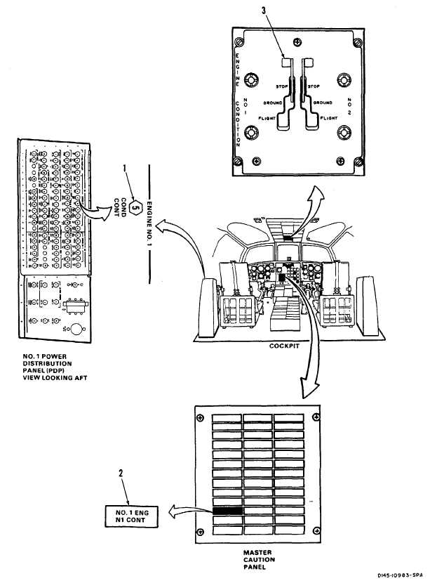
CHECK NO. 1 ENGINE GAS PRODUCER CONTROL SYSTEM
1.
Check that ENGINE NO. 1 COND CONT circuit breaker
If circuit breaker (1) is open, close it. If it opens again, go to
(1) is closed.
task 4-5.4.
2.
Check No. 1 ENG N1 CONT capsule (2).
If capsule (2) is lit, go to task 4-5.5.
3.
Open ENGINE NO. 1 COND CONT circuit breaker (1).
Fuel control pointer (4) shall not move. If it does, replace
Set NO. 1 ENGINE CONDITION lever (3) to GROUND.
No. 1 gas producer control box.
Close ENGINE NO. 1 COND CONT circuit breaker (1).
4.
Set NO. 1 ENGINE CONDITION lever (3) to STOP and
Fuel control pointer (4) shall move and stop about mid point
then to GROUND.
in ground band on protractor 95). If it does not, go to task
4-5.6. NO. 1 ENG N1 CONT capsule (2) shall come on and
stay on until fuel control pointer moves to ground position. If
capsule does not come on, go to task 4-5.7. If light comes
on and stays on, go to task 4-5.5.
5. Set NO. 1 ENGINE CONDITION lever (3) to FLIGHT.
NO. 1 ENG N1 CONT capsule (2) shall come on and stay
on until fuel control pointer (4) moves to flight band. Pointer
(4) shall make positive contact with stop (6). Rod (7) shall
compress and partially cover brown band (8). If capsule (2)
comes on and goes out and pointer (4) does not move,
replace No. 1 gas producer control actuator. If pointer (4)
moves but does not make contact with stop or brown band is
not partially covered, go to task 4-5.8.
GO TO NEXT PAGE
4-96 Change 17