TM 55-1520-240-T
4-5.3 GAS PRODUCER CONTROL SYSTEM (N1) OPERATIONAL CHECK (Continued)
4-5.3
T A S K
R E S U L T
6.
7.
8.
9.
10.
11.
12.
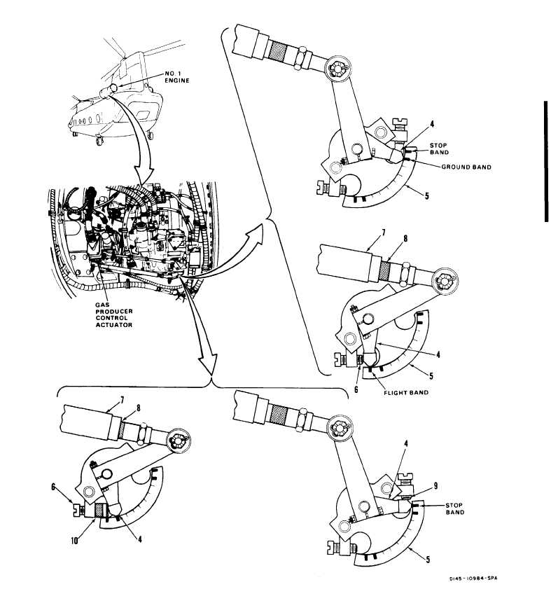
Set NO. 1 ENGINE CONDITION lever (3)
to GROUND.
Set NO. 1 ENGINE CONDITION lever (3)
to STOP.
Move NO. 1 ENGINE CONDITION lever (3)
from STOP to GROUND to FLIGHT, and
then directly from FLIGHT to STOP.
Move NO. 1 ENGINE CONDITION Iever (3)
from STOP to GROUND to FLIGHT and
then to GROUND and STOP with a pause
at each position.
Open ENGINE NO. 1 COND CONT circuit
breaker (1). Install topping stop (1 O). Do
not move stop (6) when installing topping
stop (10).
Close ENGINE NO. 1 COND CONT circuit
breaker (1). Set NO. 1 ENGINE CONDl-
TION lever (3) to FLIGHT.
Set NO. 1 ENGINE CONDITION lever (3)
to STOP. Remove topping stop (10).
Make sure topping stop is re-
moved from engine. If it is not,
engine emergency power capabili-
ty will be disabled. Damage to air-
craft or components can result.
NO. 1 ENG N1 CONT capsule (2) shall come on and
stay on until fuel control pointer (4) moves to and
stops within ground band.
NO. 1 ENG N1 CONT capsule (2) shall come on and
stay on until fuel control pointer (4) moves to stop
band on protractor (5) and is in positive contact with
stop (9). If capsule (2) is still on when pointer is
against stop (9), go to task 4-5.5.
NO. 1 ENG N1 CONT capsule (2) shall come on
when pointer (4) travels between bands. If capsule is
not on when pointer is traveling between any two
bands, go to task 4-5.7. If pointer (4) is not against
stop (9), adjust gas producer system. Refer to TM
55-1520-240-23.
Fuel control pointer (4) shall move to each corre-
sponding band on protractor (5).
Fuel control pointer (4) shall move to and be in posi-
tive contact with topping stop (10). Rod (7) shall
compress and cover brown band (8), more than in
step 5.
NOTE
Brown band shall still be visible.
GO TO NEXT PAGE
Change 4
4-97