12-2.3
TM 55-1520-240-T
12-2.3 FIRE DETECTION SYSTEM VISUAL CHECK
INITIAL SETUP
Applicable Configurations:
All
Tools:
Electrical Repairer’s Tool Kit,
N S N 5 1 8 0 - 0 0 - 3 2 3 - 4 9 15
Materials:
None
Personnel Required:
68F10 Aircraft Electrician
References:
T M 5 5 - 1 5 2 0 - 2 4 0 - 23
Equipment Condition:
T M 5 5 - 1 5 2 0 - 2 4 0 - 2 3.
Battery Disconnected
Electrical Power Off
Hydraulic Power Off
No. 1 and No. 2 Engine
Access Covers Open
1.
2.
3.
4.
5.
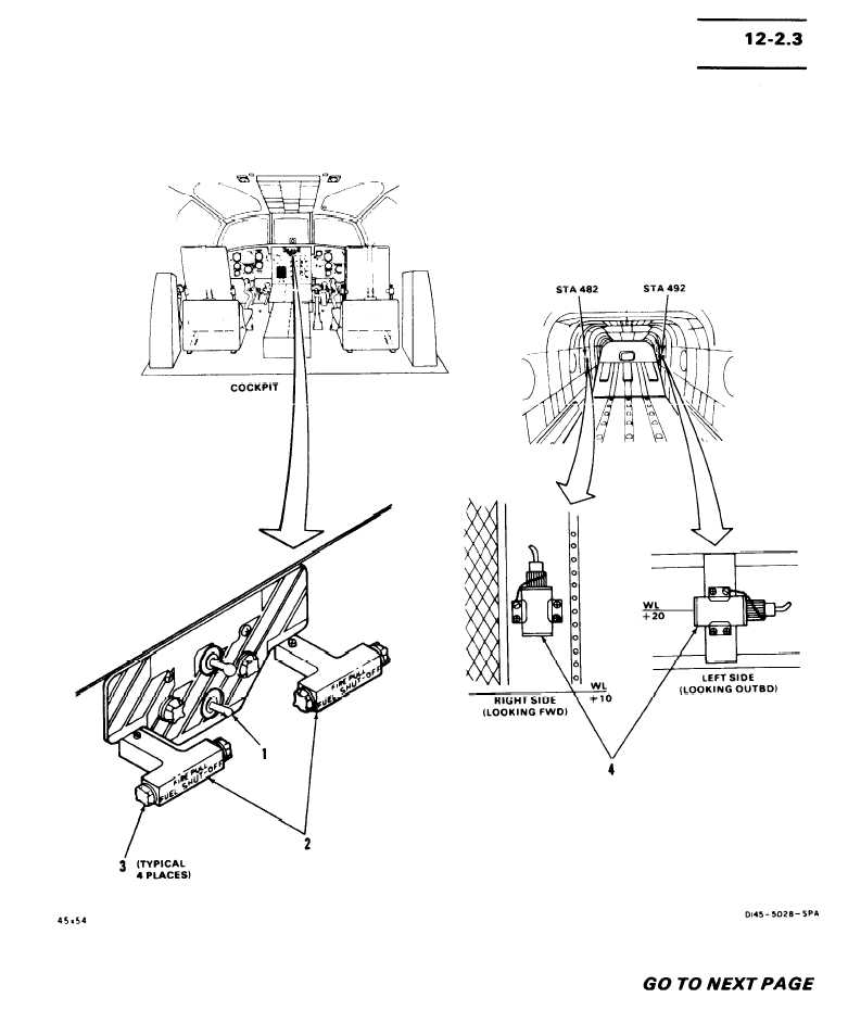
Check Fire Detector switch (1).
Check No. 1 engine and No. 2 engine fire
handles (2).
Check No. 1 and No. 2 engine fire detec-
tion controls (4).
Check sensing elements (5) around No. 1
engina.
Check sensing elements (7) around No. 2
If switch (1) is loose or damaged, tighten or re-
place it as required.
If either fire handle (2) is loose or damaged,
tighten or replace it as required, If any light (3) is
loose or damaged, tighten or replace it as re-
quired.
If either control (4) is loose or damaged, tighten or
replace it as required. If wiring to either control IS
damaged, repair or replace it as required.
If any element (5) is damaged or kinked, replace it,
If element connector (6) is loose, tighten it,
If any element (7) is damaged or kinked, replace it.
engine.
If any element connector (6) is loose, tighten it.
FOLLOW-ON MAINTENANCE:
T M 5 5 - 1 5 2 0 - 2 4 0 - 2 3:
Close No. 1 and No. 2 engine access
covers.
1 2 - 3 2


