TM 1-1520-240-10
3-3-2
CONTROLS/
INDICATOR
FUNCTION
MB SENS
Labeled HI and LO. LO
sensitivity is used for
positive identification of
marker beacon passage.
HI is used for station
passage identification at
the outer marker or en-
route.
Marker Beacon Indicator
Lights
Three lights marked 0,M,
and I on both HSI MODE
SELECT panels. Lights
illuminate when passing
over beacons.
3-3-4. Normal Operation - VHF Navigation and In-
strument Landing System. The following paragraphs
provide navigation radio set operating procedures.
a. Starting.
(1)
Interphone AUX switch - ON
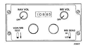
Figure 3-3-1. VHF Navigation and Instrument
Landing System Control (AN/ARN-123)
(2)
NAV VOL switch — ON.
b. VOR/Localizer/ILS Operation.
(1)
Megahertz and kilohertz selector — Set fre-
quency of facility.
(2)
VOR SEL switch on HSI MODE SELECT
panel — Press. Check SEL light lit.
(3)
VOR ADF switch on HSI MODE SELECT
panel — Press, if VOR segment is not lit
(4)
Volume control — Adjust. Identify facility
(5)
HSIs — Check for correct indications.
c. Marker Beacon operation.
(1)
MB VOL switch — ON.
(2)
MB SENS — HI for enroute. Lo for ap-
proach.
(3)
MKR BKN lamps on HSI MODE SELECT
panels — Check lit at corresponding station passage.
d. Stopping — NAV VOL and MB VOL switches —
OFF
3-3-5. Direction Finder Set (AN/ARN-89).
Direction finder set (AN/ARN-89) is an airborne automat-
ic direction finder (ADF) operating within the frequency
range of 100 to 3,000 kHz. The equipment provides visu-
al and aural facilities for ADF homing and position fixing.
It is used as a navigational radio aid to continuously and
visually indicate the magnetic bearing of a radio station
while providing aural reception. The bearing of a radio
station is displayed on the No. 2 bearing pointer on the
HSI. Power to operate the direction-finder set is supplied
by the No. 1 DC bus and the AC instrument bus through
the NAV ADF circuit breakers on the No. 1 PDP.
3-3-6. Controls and Function, Direction Finder Set
(AN/ARN-89). (fig. 3-3-2)
CONTROLS/
INDICATOR
FUNCTION
Mode Switch OFF
OFF position deener-
gizes the direction finder
set.
COMP
COMP position selects
automatic direction find-
ing.
ANT
ANT position permits re-
ception for radio naviga-
tion or as a broadcast
receiver.
LOOP
LOOP position, used in
conjunction with LOOP
switch, permits aural null
homing and manual di-
rection finding.


