TM 1-1520-240-10
3-3-4
3-3-8. Gyromagnetic Compass Set (AN/ASN-43).
The gyromagnetic compass set (fig. 3-3-3) is a direction
sensing system which provides a visual indication of the
heading of the helicopter with respect to the earth’s mag-
netic field or referenced to a free directional gyro. Head-
ing information is displayed on both HSIs. The display is
used in a navigation to maintain flight path direction.
Also, any heading selected with the heading bug on ei-
ther HSI can be automatically maintained by the AFCS.
Power to operate the system is supplied by the No. 1 AC
bus and the AC instrument bus through the NAV CMPS
circuit breakers on the No. 1 PDP.
3-3-9. Controls and Function, Gyromagnetic Com-
pass Set (AN/ASN-43). (fig 3-3-3 and 3-3-4)
CONTROLS/
INDICATOR
FUNCTION
LATITUDE Switch
Two-position switch on
the directional gyro lo-
cated on the avionics
shelf. This switch is
used to correct for gyro
precession for the hemi-
sphere of operation: N
for northern hemisphere
and S for southern
hemisphere.
LATITUDE Control Switch
Rotary control on direc-
tional gyro labeled 0 to
90. It is used to set the
local latitude into the di-
rectional gyro for free
gyro operation.
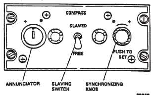
SLAVED-FREE Switch
On compass control
panel. When switch is at
SLAVED, the compass
cards on both HSIs are
slaved to the output of
the remote compass
and-stabilized by the di-
rectional gyro. At FREE,
the cards are referenced
to the directional gyro
only and act as turn indi-
cators. FREE is used
primarily in polar regions
where magnetic indica-
tions may be unreliable.
PUSH TO SET synchro-
nizing knob
Rotated in ( ) or (+) di-
rection as indicated by
annunciator pointer to
align compass cards
with gyro-compass.
CONTROLS/
INDICATOR
FUNCTION
HDG Flag
A red flag on both HSIs
indicates failure of the
gyromagnetic compass
system when displayed.
3-3-10. Operating Procedures — Gyromagnetic
Compass Set. (fig. 3-3-3)
a. Slaved Gyro Operation. With compass slaving
switch at SLAVED, the system operates in the slaved
mode and the directional gyro precesses to align the
compass cards on the HSIs with the magnetic heading
of the helicopter. During the first 2 minutes after power is
applied, the system operates in a fast slave mode while
the gyro attains its speed. After this initial alignment peri-
od is complete, the gyromagnetic compass will return to
the normal slaved mode. During this mode of operation,
the compass cards will remain aligned with the magnetic
heading of the helicopter. The annunciator pointer will
occasionally point to a dot ( ) or a plus sign (+) indicat-
ing that corrections are automatically being made.
b. Free Directional Gyro Operation. If the compass
slaving switch is at FREE, the system operates in the free
directional mode. In this mode, the compass cards can
be set to any heading by pressing the PUSH TO SET
knob and turning it until the cards reach the selected
setting. Normally, the free directional gyro mode is
employed only in polar regions of the earth where mag-
netic references are unreliable. However, it can be useful
if the slaving system malfunctions. For proper operation,
the latitude controls on the directional gyro (fig. 3-3-4)
must be set to the local latitude.
Figure 3-3-3. Gyromagnetic Compass Set Control
Panel