TM 1-1520-240-10
4-2-11/(4-2-12 blank)
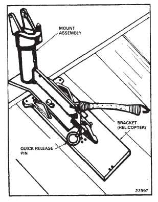
Figure 4-2-10. M41 Mount — Installed on Ramp
4-2-12. Mount Assembly (M41).
The mount is positioned on the lugs of the ramp bracket
and is secured with a quick-release pin (fig. 4-2-10).
NOTE
If the bracket must be installed, be sure to center it along
the rear edge of the loading ramp.
4-2-13. Mount Assembly Stops, Cams, Quick-Re-
lease Pin, and Elastic Cord (M41).
The mount stops, cams, quick-release pin, and elastic
cord have the following functions:
a.
Maximum traverse, elevation, and depression of
the machine gun M60D are controlled by cam surfaces
and stops on the pintle and the pintle post (table 4-2-3).
b.
The quick-release pin, attached by cable to the
rear of the mount, secures the mount to the ramp (fig.
4-2-10).
c.
The elastic cord is fastened to the mount and the
machine gun when holding it in a stowed position.
Table 4-2-3. Armament Subsystem M41 Data
Effective range
1100 meters (max)
Rate of fire
550-650 rnds per min.
Length, overall
44.875 in.
Sighting
Aircraft ring and post type
Total traversing capability
94_
Elevation
12_30’
Depression
69_
4-2-14. Operation — Armament Subsystem M41
Operation of the armament subsystem M41 is the same
as operation of the M24.